Download
1 / 5
50 likes | 58 Views
Lab 15 :BCD Counters and Frequency Division:. Slide 2. BCD Numbers. Slide 3. MOD 100 BCD Counter. Slide 4. Frequency Division. Slide 5. Frequency Division and the UP-1 board. 1 0 1 0. 1 0 1 1. 0 1 0 1. 0 0 0 0. 0 0 0 1.

E N D
Lab 15 :BCD Counters and Frequency Division: Slide 2 BCD Numbers. Slide 3 MOD 100 BCD Counter.. Slide 4 Frequency Division Slide 5 Frequency Division and the UP-1 board.
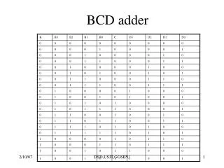
1 0 1 0 1 0 1 1 0 1 0 1 0 0 0 0 0 0 0 1 0 1 1 1 1 0 0 1 0 0 1 1 0 1 1 0 0 1 0 0 1 0 0 0 0 0 1 0 =1 =7 =6 =8 =9 =5 =4 =3 =2 =0 8 4 bit numbers for 10, 11, … 15 are not used! 4 2 1 1 1 0 0 1 1 0 1 1 1 1 0 1 1 1 1 Lab 15: BCD Numbers : A BCD number is a Binary Coded Decimal number. It is a 4 bit code used to represent the decimal numerals 0, … 9. The 4 bit numbers above 9 are not used in this number system. Converting decimal to BCD: Example: convert 25 to BCD Convert each decimal numeral to BCD. 2 5 0010 0101 Thus 25 = 00100101BCD Converting BCD to decimal : Example: convert 0110010111BCD to decimal.Start at the BCD point and group BCD bits into blocks of four. Convert each block into a BCD number. 0110010111 7 9 1 Thus 0110010111BCD = 197 Slide #2
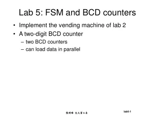
4count 4count LDN LDN A A B B QA QA C C QB QB D D QC QC 0 CIN CIN QD QD DNUP DNUP COUT COUT 0 0 0 0 0 0 SETN SETN 1 CLRN CLRN CLK CLK Lab 15: Mod 100 BCD Counter: A MOD 100 BCD counter is made up of two 4count symbols. Each 4count symbol is a MOD 10 counter. Here is the first Mod 10 counter. 0 1 0 1 0 0 0 0 0 0 1 0 1 0 1 0 0 1 1 0 0 0 0 1 1 1 0 1 1 0 0 1 0 1 0 0 0 0 0 0 0 0 0 0 1 0 0 0 0 1 1 0 0 0 1 0 0 1 1 0 1 0 0 0 1 1 0 0 0 0 0 0 0 1 1 1 1 0 0 The NAND gate will output a 1 when the count is 0 to 9. The NAND gate will output a 0 when the feedback condition 10 is reached. This will re-start the counter at 0. Add a second MOD 10 counter. Connect the clocks together. Connecting COUT and CIN will not work. COUT of the first counter is 1 when the counter reaches 15. At 15 the first counter signals the CIN of the second counter to count up by one on the next clock pulse. 15 is the terminal count which is never reached by a MOD 10 counter. An AND gate connected to CIN of the second stage is required. The inputs of the AND gate connects to QA and QD of the first counter. QA and QD are 1 when the counter is 9. This is the terminal count for a MOD 10 counter. Start the count at 0. Both NAND gates are 1 and the AND gate is 0 when the count is 0 to 8. The first counter counts the second counter holds 0 because CIN=0. Skip ahead in the count to 8. At 9 the AND gate outputs a 1 to CIN. The next clock pulse will create the feedback condition for the first counter. CIN =1 for the second counter means the its count goes to 1. Slide #3 This cycle repeats itself at 19, 29 … The counter counts from 0 to 99 in BCD
8 PPS Input J Qa J Qb J Qc 1 1 PPS >Clk >Clk >Clk K Qa K Qb K Qc 1 0 1 2 3 4 5 6 7 8 PPS 4 PPS Mod 8 counter is also called a divide by 8 counter Qa 2 PPS Qb 1 PPS Qc 1 Second Lab 15 : Frequency Division: Frequency of a pulse waveform is its pulse rate. A counter halves the frequency of the input clock at each of its outputs. Slide #4
UP-1 The counter requires 16 clock pulses to count from 0 to 15. Each second the oscillator generates 25,175,000 pulses. LED’s are changing so fast that they all appear to be on at the same time. Oscillator 25,175,000 PPS Q0 Mod 16counter with a 25,175,000 PPS clock rate. Mod 16 counter with a 12,587,500 PPS clock rate. Mod 16 counter with a 3,146,875 PPS clock rate. Mod 16 counter with a 6,293,750 PPS clock rate. Mod 16 counter with a 48 PPS clock rate. Mod 16 counter with a 24 PPS clock rate. Mod 16 counter with a 12 PPS clock rate. Q1 Q2 QA Q3 >CLK QB Q4 QC Q5 QD Q6 Q7 UP-1 Q8 Oscillator Q9 >CLK Q10 Q11 Q12 25,175,000 PPS Q13 Q14 Q15 Q16 Q17 Q18 24 PPS Q19 12 PPS Q20 6 PPS Q21 Visible on LED’s! 3 PPS Q22 1.5 PPS Q23 0.75 PPS Q24 Lab 15 : Frequency Division and the UP-1 board: The UP-1 board has a 25,1275,000 PPS oscillator. Connecting a counter to a set of LED’s and clocking the counter at this fast rate would result in a count that would not be distinguishable on the LEDS. All LED’s would appear to be on at the same time. Connecting the UP-1 oscillator to a 24 stage counter will divide the frequency down to a rate that is distinguishable on LED’s. Grouping any 4 adjacent outputs creates a MOD 16 counter. Each MOD 16 counter group counts a slower speed. Pulse rates must be less than 30 PPS in order to be distinguishable on LED’s. Slide #5