Download
1 / 25
260 likes | 351 Views
Aligning the vacuum reflectometer. Stephen harman. Our research. Analyzing surface roughness using extreme ultraviolet light. Why study extreme ultraviolet?. More precise analysis of surface roughness. Make smaller, faster, and cooler computer chips. Astronomical Bodies

E N D
Aligning the vacuum reflectometer Stephen harman
Our research • Analyzing surface roughness using extreme ultraviolet light.
Why study extreme ultraviolet? • More precise analysis of surface roughness. • Make smaller, faster, and cooler computer chips. • Astronomical Bodies • Earth’s magnetosphere • Blackholes
About extreme ultraviolet • The wavelength of extreme ultraviolet light is about 1 to 60 nm. • Absorbed very quickly by any medium.
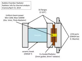
Reflectometer layout Slits Plasma Grim Hollow Cathode
Inside Chamber Detector Pinhole Mirror
Channel electron multiplier (CEM) Photoelectric Effect Resistive Photosurface Photon 2000 V 800 V 105-107 Electrons
Initial problem detected • Maximum photon count was 264. We need tens of thousands of counts.
Desired Calibration • Extreme ultraviolet light will go through the first slit, diffract off of GRIM, go through a second slit, go through the pinhole, and reflect off of the mirror into the detector. • Light goes through the center of Octopus. • Light continues to hit the center of Octopus regardless of what position the light hits GRIM. • When light hits center of GRIM, put pinhole and detector in the correct location.
Calibration Process • Open Octopus, GRIM, and both slits. • Removed pinhole. • Removed glass tube connected to hollow cathode. • Shine laser through the hollow cathode into the system.
Laser position in octopus • Ensure laser goes through chamber center.
Inside Chamber Detector Pinhole Mirror
Centering • Scan mirror in the z direction. y x z
Centering • Mirror rotation scan. θ
Centering • Scan detector.
Centering • We are aligned and centered when… • Theta and detector scans have similar peaks and FWHM • Theta scan is in the shape of an upside down “V” • Now to verify we are going to do a θ 2θ scan. • Set the mirror to some angle θ and scan the detector across the angle 2θ. • Peak should be close to or at the angle 2θ.
Picture of theta scan • Set the mirror to some angle θ and scan the detector across the angle 2θ. Mirror XUV Light θ θ Detector θ
Verify alignment Detector scan with θ = 5°.
Verify alignment Detector scan with θ = 20°.
Verify alignment Detector scan with θ = 30°.
Our research possibilities • More precise analysis of surface roughness. • Make smaller, faster, and cooler computer chips. • More understanding of astronomical bodies • Earth’s magnetosphere • Blackholes
Acknowledgements • Dr. Steven Turley • Cody Petrie • Lexi Bach