Download
1 / 89
990 likes | 1.39k Views
An Overview of GSM. Introduction of GSM GSM Spectrum Mobile Station GSM Sub Systems NSS BSS NMS GSM Interfaces Channel Concepts. GSM:A brief background.

E N D
An Overview of GSM • Introduction of GSM • GSM Spectrum • Mobile Station • GSM Sub Systems NSS BSS NMS • GSM Interfaces • Channel Concepts
GSM:A brief background • At the beginning of the 1980s a problem was that the European countries were using many different, incompatible mobile phone systems. These systems are referred to as 1G (first generation) systems. • In Europe, the most common 1G system was NMT (Nordic Mobile Telephone) and TACS (Total Access Communications System). In the United States, as well as in other American countries, AMPS (Advanced Mobile Phone System) was, and still is, a widely established system.
GSM:A brief background • With the passage of time, the need for telecom services was remarkably increased. Due to this, CEPT (Conférence Européenne des Postes et Télécommunications) founded a group to specify a common mobile system for Western Europe. • This group was named “Groupe Spéciale Mobile” and the system name GSM arose. This abbreviation has since been interpreted in other ways, but the most common expression nowadays is Global System for Mobile communications. • GSM is a 2G (second generation) system.
Expectations From GSM System • The GSM system must be an open system. • The system should be able to support several network operators in each country. • GSM networks must be built without causing any major changes to the already existing Public Switched Telephone Networks (PSTN).
Expectations From GSM System • The system must be Pan European. • The system must maintain a good speech quality. • The system must use radio frequencies as efficiently as possible. • The system must have high / adequate capacity. • The system must be compatible with ISDN and other data communication specifications. • The system must maintain good security both for subscriber and transmitted information.
Advantages Of GSM • GSM uses radio frequencies efficiently, and due to the digital radio path, the system tolerates more inter - cell disturbances. • The average speech quality is better than in analogue systems. • Data transmission is supported throughout the GSM system. • Speech is encrypted and subscriber information security is guaranteed. • With ISDN compatibility, new services are offered. • International roaming is technically possible within all countries using the GSM system. • The large market increases competition and lowers the prices both for investments and usage.
Requirement Of Telecom Network • A connection between two people − a caller and the called person − is the basic service of all telephone networks. • To provide this service, the network must be able to set up and maintain a call, which involves a number of tasks: • Identifying the called person. • Determining the location. • Routing the call. • Ensuring that the connection is sustained as long as the conversation lasts. • After the transaction, the connection is terminated and (normally) the calling user is charged for the service he has used.
Requirement Of Mobile Telecom Network • In a mobile network, however, the establishment of a call is a far more complex task, as the wireless (radio) connection enables the users to move at their own free will − providing they stay within the network's service area. • In practice, the network has to find solutions to three problems before it can even set up a call.
Requirement Of Mobile Telecom Network • In other words, the subscriber has to be LOCATEDand IDENTIFIEDto provide him/her with the requested services. • In order to understand how we are able to serve the subscribers, it is necessary to identify the main interfaces, the subsystems and network elements in the GSM network, as well as their functions.
UPLINK DOWNLINK B T S GSMUplink & Downlink • Frequency Bands GSM 900 Mhz Uplink 890-915 Mhz Down Link 935-960 Mhz
890Mhz 915Mhz 935Mhz 960Mhz UP Link Down Link . . . . . . . . . . . . 890 890.2 914.8 915 935 935.2 959.8 960 124 carriers 124 carriers
GSM Specifications RF Spectrum : GSM 900 Mobile to BS (UP-LINK) - 890 to 915 MHz BS to Mobile (DOWN -LINK) - 935 to 960 MHz Bandwidth - 25 MHz GSM 1800 Mobile to Cell (UP-LINK) - 1710 to 1785 MHz Cell to Mobile (DOWN -LINK) - 1805 to 1880 MHz Bandwidth - 75 MHz
1 2 3 4 5 6 124 Freq Mhz. 890.2 890.4 890.6 890.8 914.8 891.0 GSM - MULTIPLE ACCESS • Each RF carrier 200khz apart • Total 124 RF Channels available. • One or more carrier assigned to each base station ……...
Absolute Radio Freq Carrier Number (ARFCN) 1and 124 not used • until it is co-ordinated with Non -GSM operators in adjacent freq. bands. • Thus for practical purposes only 122 RF Carriers are available. • Frequency for any ARFCN ( n) can be calculated from : F up-link (n) = 890.2 +0.2* ( n-1 ) MHz F down-link (n) = 935.2 +0.2* ( n-1 ) MHz Here 1 ≤ n ≤ 124.
890 915 935 960 25 MHz 25 MHz 1 2 1 2 0 0 Mobile to Base Base to Mobile (MHz) 890.4 890.6 935.4 935.6 890.2 935.2 200 kHz 200 kHz 45MHz Channel layout and frequency bands of operation GSMFDMA
8 8 7 7 6 6 5 5 4 4 3 3 2 2 1 1 GSMTDMA Amplitude 45 MHz Frequency F1 (Cell Rx) F2 F1’ (Cell transmit) F2’ Typical TDMA/ FDMA frame structure
TDMA Frame Physical Channel (0.577ms) The TDMA frame time slot of 0.577ms is known as physical channel while the contents of physical channel according to their roles are called as logical channel
Mobile Station (MS) • In GSM, the mobile phone is called Mobile Station (MS). • The MS is a combination of terminal equipment and subscriber data. • The terminal equipment as such is called ME (Mobile Equipment) and the subscriber's data is stored in a separate module called SIM (Subscriber Identity Module). • Therefore, ME + SIM = MS.
MS : SIM SIM Contains: • Identification numbers of the user (IMSI). • Tools needed for authentication and ciphering. • Storage space for messages, such as phone numbers. • List of available networks
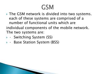
Subsystems in GSM The GSM network is called Public Land Mobile Network (PLMN). It is organised in three subsystems: • Base Station Subsystem (BSS) • Network Switching Subsystem (NSS) • Network Management Subsystem (NMS)
Function of NSS The main functions of NSS are: • Call control :This identifies the subscriber, establishes a call and clears the connection after the conversation is over. • Charging:This collects the charging information about a call such as the numbers of the caller and the called subscriber, and the time and type of the transaction, and transfers it to the Billing Centre. • Mobility management :This maintains information about the location of the subscriber. • Signalling :This applies to interfaces with the BSS and PSTN. • Subscriber data handling :This is the permanent data storage in the HLR and temporary storage of relevant data in the VLR. • Locating the subscriber before establishing a call.
NSS Elements • Mobile services Switching Centre (MSC) • Gateway Mobile services Switching Centre (GMSC) • Visitor Location Register (VLR) • Home Location Register (HLR) • Authentication Centre (AC) • Equipment Identity Register (EIR)
NSS Element : MSC Functions of MSC: Call control : identification of the type of call, the destination, and the origin of a call. It also sets up, supervises, and clears connections. Initiation of paging : Paging is the process of locating a particular mobile station in case of a mobile terminated call (a call to a mobile station). Charging data collection : The MSC generates CDRs, Charging Data Records, which contain information about the subscribers’ usage of the network.
NSS Element : GMSC • The GMSC is responsible for the same tasks as the MSC, except for paging. It is needed in case of mobile terminated calls. • In GSM, the MSC, which is serving the MS may vary due to subscriber’s mobility. Therefore, in a mobile terminated call, the call is set up to a well defined exchange in the subscriber’s home PLMN. This exchange is called GMSC. • The GMSC than interacts with a database called Home Location Register, which holds the information about the MSC, which is currently serving the MS. The process of requesting location information from the HLR is called HLR Interrogation.
NSS Element : VLR VLR is a temporary database which contains information about subscribers currently being in the service area of the MSC/VLR, such as: • Identification numbers of the subscribers. • Security information for authentication of the SIM card and for ciphering. • Services that the subscriber can use.
NSS Element : VLR • The VLR carries out location registrations and updates. When a mobile station comes to a new MSC/VLR serving area, it must register itself in the VLR, in other words perform a location update. • A mobile subscriber must always be registered in a VLR in order to use the services of the network. • The VLR database is temporary, in the sense that the data is held as long as the subscriber is within its service area. It also contains the address to every subscriber's Home Location Register.
NSS Element : HLR HLR maintains a permanent database of the subscribers. The following date related to the subscriber can be found here: • Subscriber identification number (IMSI) • The subscribed services. • The current location of its subscriber in terms of VLR address.
NSS Element : AC • The Authentication Centre provides security information to the network, so that the mobile network can verify the SIM cards (authentication between the MS and the VLR) and cipher the information transmitted in the air interface (between the MS and the BTS). • The Authentication Centre supports the VLR's work by issuing so-called authentication triplets upon request (RAND, SRES, and Kc).
NSS Element : EIR • The Equipment Identity Register is used for security reasons. • EIR is responsible for IMEI checking (checking the validity of the mobile equipment). • When this optional network element is in use, the mobile station is requested to provide the International Mobile Equipment Identity (IMEI) number. The EIR contains three lists: - White list - Grey list. - Black list.
Base Station Subsystem (BSS) The BSS is responsible for managing the radio network, and it is controlled by an MSC. Typically, one MSC contains several BSSs. A BSS itself may cover a considerably large geographical area consisting of many cells (a cell refers to an area covered by one or more frequency resources). The BSS consists of the following network elements: • BSC (Base Station Controller ) • BTS (Base Transceiver Station ) • TRAU (Transcoder and Rate Adaptation Unit referred to as TC (Transcoder))
Function of BSS • Radio Path Control: BSS takes care of radio resources, that is, radio channel allocation and quality of the radio connection. • Synchronisation :MSC synchronises the BSC, and the BSC further synchronises the BTSs associated with that particular BSC. Inside the BSS, synchronisation is controlled by the BSC. • Air- and A-interface signalling :In order to establish a call, the MS must have a connection through he the BSS. • Connection establishment between the MS and the NSS. • Mobility Management and Speech Transcoding :BSS mobility management mainly covers the different cases of handovers.
BSS Element : BSC Functions of BSC: • Connection establishment between the MS and the NSS: All calls to and from the MS are connected through the switching functionality of the BSC. • Mobility management : Keeps track of MS and responsible for initiating the vast majority of all handovers. It makes the handover decision based on measurement reports sent by the MS during a call. • Statistical raw data collection:Information from the BTS, Transcoders, and BSC are collected in the BSC and forwarded via the DCN (Data Communications Network) to the NMS (Network Management Subsystem), where they are post-processed into statistical views, from which the network quality and status is obtained.
BSS Element : BSC Functions of BSC: • Air- and A-interface signalling support: In the A-Interface, SS#7 is used as the signalling language, while the environment in the Air-Interface allows the usage of a protocol adapted from ISDN standards, namely LAPDm (Link Access Protocol on the ISDN D Channel, modified version). Between the BTS and the BSC (Abis Interface), a more standardised LAPD protocol is used. The BSC also enables the transparent signalling connection needed between the MSC/VLR and the MS. • BTS and TRAU control : Inside the BSS, all the BTSs and TCs are connected to the BSC(s). The BSC maintains the BTSs and is capable of separating (barring) a BTS from the network and collecting alarm information. TRAUs are also maintained by the BSC.
BSS Element : BTS BTS is responsible for maintaining the Air-Interface and minimising the transmission problems. BTS functions are as follows: • Air interface signalling • Ciphering:Both the BTS and the MS must be able to cipher and decipher information in order to protect the transmitted speech and data in the air interface. • Speech processing : All functions performed by BTS in order to guarantee an error-free connection between the MS and the BTS. This includes: • Speech Coding: D/A conversion in the downlink direction and vice-versa. • Channel Coding: Used for error protection against fading dips. • Interleaving: Spreading the coded speach in many Bursts to enable a secure transmission. • Burst Formatting: Adding information to the coded speech / data in order to achieve a well-organised and safe transmission. • GMSK Modulation and Demodulation.
BSS Element : BTS • The BTS can contain several TRXs (Transceivers), each supporting one pair of frequencies for transmitting and receiving information. • The BTS also has one or more antennas, which are capable of transmitting and receiving information to/from one or more TRXs. The antennas are either omnidirectional or sectorised. • BTS also has control functions for O & M, synchronisation and external alarms, etc.
BSS Element : TRAU TRAU performs two main functions: • Conversion from one speech compression format to another. • DTX (Discontinuous transmission) which is used during a call when there is nothing to transmit (no conversation). It is activated in order to reduce interference and to save MS battery.
BSS Element : TRAU • In GSM 900/1800 specifications, bit rate in Air-Interface is 13 Kbps (Full rate) and bit rate in the MSC and PSTN interface is 64 Kbps. Transcoder converts 13 Kbps to 64 Kbps and vice-versa. TC belongs to BTS but it is kept near MSC to save the transmission media. 64 Kbps from MSC is converted into 16 Kbps(13 Kbps for speech + 3 Kbps for signaling) after TC and Submultiplexure puts 4 such 16 Kbps streams on 64 Kbps standard PCM channel to be carried towards BSC. Thus 4 PCMs from MSC side goes on single PCM towards BSC after TCSM unit. Due to this TCSM(TRAU) is kept near MSC.
Network Management Subsystem (NMS) • The purpose of the NMS is to monitor various functions and elements of the network. • The functions of the NMS can be divided into three categories: - Fault management - Configuration management - Performance management • These functions cover the whole of the GSM network elements from the level of individual BTSs, up to MSCs and HLRs.
NMS : Fault Management The purpose of fault management is to: • ensure the smooth operation of the network and rapid correction of any kind of problems that are detected. • provides the network operator with information about the current status of alarms, events and maintains a history database of alarms. The alarms are stored in the NMS database and this database can be searched according to criteria specified by the network operator.
NMS : Configuration Management The purpose of configuration management is to maintain up-to-date information about the operation and configuration status of network elements. Specific configuration functions include the management of the radio network, software and hardware management of the network elements, time synchronisation, and security operations.
NMS : Performance Management In performance management, the NMS collects measurement data from individual network elements and stores it in a database. On the basis of these data, the network operator is able to compare the actual performance of the network with the planned performance and detect both good and bad performance areas within the network.
GSM Interfaces • One of the main purposes behind the GSM specifications is to define several open interfaces. Due to this operator maintaining the network may obtain different parts of the network from different GSM network suppliers. • The GSM specifications define two truly open interfaces within the GSM network. The first one is between the Mobile Station (MS) and the Base Station (BS). This open-air interface is called Um. • The second interface is located between the Mobile services Switching Centre, MSC and the Base Station Controller (BSC). This interface is called the “A-interface”.