Download
1 / 109
1.09k likes | 1.27k Views
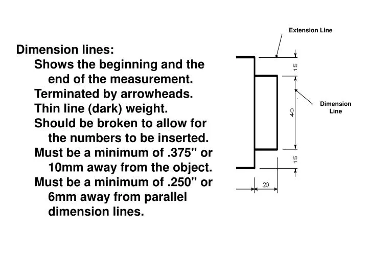
Extension Line. Dimension lines: Shows the beginning and the end of the measurement. Terminated by arrowheads. Thin line (dark) weight. Should be broken to allow for the numbers to be inserted. Must be a minimum of .375" or 10mm away from the object.

E N D
Extension Line • Dimension lines: • Shows the beginning and the end of the measurement. • Terminated by arrowheads. • Thin line (dark) weight. • Should be broken to allow for the numbers to be inserted. • Must be a minimum of .375" or 10mm away from the object. • Must be a minimum of .250" or 6mm away from parallel dimension lines. Dimension Line
Extension Line • Extension lines: • Extend the edge of the object. • Thin line (dark) weight. • There should be a visible gap (.0625" or 1mm) between the object and the start of the extension line. • Extension lines should extend about .125" or 2.5mm beyond the last dimension line. Dimension Line
Leader lines: • Are drawn from a note or dimension to place where the note applies. • Are drawn at an angle (usually 30°, 45°, or 60°). • Should have a short (.125" or 3mm) shoulder that if extended, would intersect the note at mid-height. • May end with an arrowhead or dot. • Leaders should not cross over or through other leaders or dimension lines. • Avoid making leaders parallel or perpendicular to visible edges. • .
Arrowheads: • Can be solid filled or open. • Should be approximately .125" or 3mm long. • Should be approximately 2.5 to 3 times as long as wide.
1. Phantom 2. Section 3. Hidden 4. Cutting/viewing 5. Leader 6. Hidden 7. Center 8. Visible/object 9. Extension 10. Break 11. Visible/object 12. Section 13. Extension 14. Break 15. Dimension
Procedures for using decimal and metric measurement. • Decimal inches: • Decimals are the ANSI standard. • Decimals are easier to add, subtract, multiply and divide than fractions. • Preferably, decimals should be rounded to two decimal places. Omit zero before the decimal point for values of less than one. • Fractional inches: • Used where close tolerances are not important. • The horizontal fraction bar is preferred. • Metric: • Where linear measurement are less than 10,000 millimeters, the millimeter is the standard unit of measure. • The abbreviation for millimeters (mm) is usually omitted when all dimensions are in millimeters. • The period is used as a decimal point only in English speaking countries, others use a comma.
The number one rule of dimensioning is that of clarity. • Place dimensions where the shape is best shown. • Shortest dimensions placed closest to the object. • Group and align dimensions when possible. • Avoid duplicate and/or unnecessary dimensions. • Try to avoid placing dimensions inside a view. • Avoid crowding dimensions. • Avoid dimensioning to hidden features. • Place dimensions between the views to which they relate. • Lines should be thin and contrast noticeably with visible lines. • Dimensions should be included that describe both size and location of features. • The diameter of cylinders is dimensioned in the rectangular view. The diameter of machined holes is dimensionedin the circular view.
Polar CoordinatesPolar coordinates used when you need to draw the next points at specify angle. Polar coordinates system in AutoCAD specifies distance length at which angle. Using polar coordinate, points entered by typing @distance<angle [Enter] Polar Coordinate System
Absolute Coordinate System Relative CoordinatesAfter first points entered, your next points can be entered by specifying the next coordinate compare/relative from the first points. The relative coordinate started with symbol “@” tell AutoCAD it was a relative coordinates. Using relative coordinate, points entered by typing @x,y [Enter]
Boolean Commands. • Union (+ or ) – adds parts together • Subtract or Difference ( ) – removes parts or features • Intersection ( * or ) – Intersects overlapping volumes into a single feature
Purpose of a Sketch • Quickly & easily get an idea on paper • Design sketches • Freehand technical sketches • Technical illustrations
Sketching Lines • Vertical lines • Top to bottom • Long straight lines • Series of short straight lines
Sketching Circles & Arcs • Begin by lightly constructing a square
Sketching Angles • Begin with 90°angle 45° 60° 30° Subdivide once Subdivide twice
Sketching • Types of Sketches • Single-view • Multi-view • Pictorials
Single-view Sketching • Technical purposes • Front view • Most descriptive features
Multi-view Sketching • Technical sketch • Front view • Top view • Side view
Pictorial Sketches • Quickly communicate an idea • Three dimensions in one view • Width • Height • Depth
Pictorial Sketches • Three (3) types • Isometric • Oblique • Perspective
Isometric Sketch HEIGHT WIDTH DEPTH
Isometric Sketching • Three equally spaced axes of 120°
Isometric Sketching • Receding lines • Typically 30° off horizontal
Isometric Sketching • Circular shapes appear as ellipses
Isometric Ellipses • Correct ellipse orientation
Isometric Sketching • Non-Isometric lines • Locate endpoints and connect
Oblique Sketch HEIGHT DEPTH WIDTH
Oblique Sketching • Front view is drawn true shape and size
Oblique Sketching • Receding edges are usually drawn at an angle of 30°, 45°, or 60°
Oblique Sketching • Circles and curves drawn on frontal plane will appear true shape and size
Perspective Sketches 1-Point Perspective 2-Point Perspective
Perspective Sketches • Objects appear as the eye would see them • Most realistic type of pictorial sketch • Most difficult pictorial sketch to draw
Drafting Equipment • Drawing board/table
Drafting Equipment • Drawing Horizontal lines • T-square • Parallel edge • Drafting Machine • Arm/elbow type • Track type
Drafting Equipment - Triangles • 45° Triangle • Draw vertical lines and lines @ 45° • 30° x 60° Triangle • Draw vertical lines and lines @ 30° and 60° • Adjustable Triangle • Draw lines @ 0° to 90°
5B 4B 2B 3B 3H 2H H F HB B 6B 6H 5H 8H 9H 4H 7H Drafting Equipment - Leads SOFT Very soft leads, smudge easily. Used for art work of various kinds and full-size details in architectural drawing. MEDIUM General purpose work. Softer grades (right) used for technical sketching, lettering, freehand work. Harder grades (left) used for line work on machine & architectural drawings. HARD Used where extreme accuracy is required. Softer grades (right) used for line work on engineering drawings. Draw very light lines.
Drafting Equipment - Scales • Engineer (Civil) • Mechanical drafter • Metric • Architecture
Drafting Media Types • Vellum • Tracing paper treated to make it more transparent • Most commonly used drafting media • Polyester drafting films (mylar) • Very transparent, strong, and lasting • Strongest drafting media • Bond • Standard printing and copy paper
Drafting Media Sizes E – 44 X 34 48 X 36 D – 34 X 22 36 X 24 C – 22 X 17 18 X 24 B – 17 X 11 12 X 18 A – 11 X 8.5 9 X 12
Lettering • Practice of adding clear, concise words on a drawing to help people understand the drawing • Notes lettered on rough sketches are functional and important to operation • Simple freehand lettering completes the idea captured in a sketch
Lettering Composition • Letter and word spacing should be about uniform • Space between words should equal the approximate width of the letter “O” • Background area between letters should appear equal
Guidelines • Horizontal guidelines keep letters the same height • Vertical guidelines aid the eye in keeping letters from slanting • Guidelines are drawn very light and very thin • Do not need to be erased • Uniform vertical space should be left between lines of letters
Types of Lettering • ANSI(American National Standards Institute) • Recognizes the use of single-stroke Gothic letters • Letters are formed using a series of strokes • Typically all capital letters are used • Most common lettering on Engineering Drawings • Vertical, Uppercase, Gothic
1 6 2 Lettering Standards • Typically, most letters are .125” (3mm) tall • Fractions are typically twice as tall as numbers • Fraction bar is horizontal and does not touch the numbers