Download
1 / 18
180 likes | 289 Views
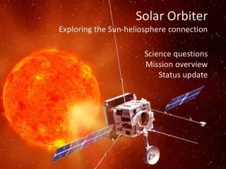
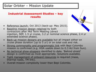
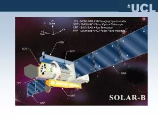
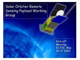
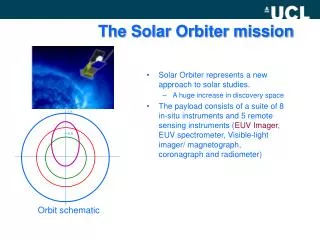
Solar Orbiter EUV Spectrometer. Thermal Design Considerations Bryan Shaughnessy. The Thermal Challenge. Reject heat input to instrument of order 100 W at 0.2 AU Maintain sensible temperatures through the solar encounter Reduce heat loss when instrument is further from the Sun.

E N D
Solar Orbiter EUV Spectrometer Thermal Design Considerations Bryan Shaughnessy
The Thermal Challenge • Reject heat input to instrument of order 100 W at 0.2 AU • Maintain sensible temperatures through the solar encounter • Reduce heat loss when instrument is further from the Sun
Spacecraft Thermal Interface • Preliminary interfaces (SCI-A/2005-307/SO/AJ Issue 1): • Instrument contained within spacecraft • Cold finger interface provided for detector cooling • Interfaces to fluid loops/heat pipes for hot elements. • Spacecraft rejects heat using louvered radiators (ESA CDF study) • Radiators likely to needed embedded heat-pipes or loop heat pipes to distribute heat. • Modelling assumptions • 50 W/K thermal link from interfaces to radiator • Radiator efficiency 90% • Louvers : Fully open at 40C; effective emissivity 0.7 Fully closed at 20C; effective emissivity 0.1
Instrument Configuration • Normal Incidence (baseline) • Uncoated SiC or Au coated SiC primary mirror (for medium/long wavelengths) • Solar absorptivity ~ 0.8 • Au coated SiC primary mirror (for medium/long wavelengths) • Solar absorptivty ~ 0.1 • Multilayer coated SiC primary mirror (for short wavelengths) • Solar absorptivity ~ 0.4 - 0.6 • Grazing Incidence (backup) • Coated SiC optics (short, medium and long wavelengths) • Solar absorptivity ~ 0.5 - 0.6
PRIMARY MIRROR ENTRANCE BAFFLE HEAT STOP / HEAT REJECTION MIRROR HEAT REJECTION I/F (HOT) HEAT REJECTION I/F (COLD) DETECTOR THERMALLY ISOLATED ENCLOSURE Normal Incidence Thermal Concept
BAFFLE HEAT STOP ENTRANCE BAFFLE DETECTOR THERMALLY ISOLATED ENCLOSURE HEAT REJECTION I/F (HOT) HEAT REJECTION I/F (COLD) Grazing Incidence Thermal Concept
Basic Thermal Requirements • Detector temperature: < -60 C (target -80 C) • Optics: < 100 C assumed • Coatings (if used) are limiting factor • Hot heat rejection interface < +50 C • Assuming NH3 heat-pipes
Primary Mirror flexible thermal link • High conductance flexible thermal link required: • Alignment with spacecraft interfaces • Allow PM scanning • Assume PM can operate hot (~ 100 C) but spacecraft interface limited to 50 C : • Conductance required: ~ 1.6 W/K (NI with absorbing PM) • Approximately 180 x 0.1 mm Al foils (25 mm wide, 50 mm length) and bolted clamps • Careful design required • Thermally induced deformation of mirror surface • Need to ensure that spacecraft interface is not heated above is maximum temperature requirement • Similar link could be used for all heat rejection interfaces
Primary Mirror flexible thermal link Bolted clamp between foil bundle and PM interface plate PM interface plate Strap interface to spacecraft heat rejection point Foils PM
Thermal Predictions • ESATAN/ESARAD thermal models have been developed for the NI and GI configurations • Predictions presented for NI (absorbing PM) and GI • Further assumptions: • No MLI around instrument • Spacecraft conductive/radiative interfaces temperatures 40 C (Hot) and 0 C (Cold) • Detector dissipation 1.6 W • NI configuration assumes mirror at heat stop reflects unwanted radiation out of instrument
Note variation over the 30 day (+/- 15 day) observation period Orbital Solar Load Variation
Conclusion • Thermal design concepts outlined for EUS • Thermal design is highly dependent on spacecraft thermal interfaces • Heat sink temperature requirements • Variation in heat rejection, especially over solar encounter period • Critical areas: • Design of high conductance flexible straps, particularly interfaces to optical surfaces (i.e., thermal distortion) • Feasibility of ‘heat rejection mirrors’ • Qualification of coatings (if used) • Intensity of solar beam at heat-stop if reflective primary mirror used