Download

1 / 46
460 likes | 554 Views
Investigating Low Impact Development Opportunities for Kelly Field Building 171. Capt Josh R. Aldred, P.E. The University of Texas at Austin. Overview. Purpose Existing Site Conditions Hydrology of Proposed Development Low Impact Development (LID) Opportunities Remaining Work Questions.

E N D
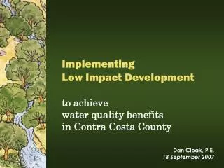
Investigating Low Impact Development Opportunities for Kelly Field Building 171 Capt Josh R. Aldred, P.E. The University of Texas at Austin
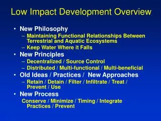
Overview • Purpose • Existing Site Conditions • Hydrology of Proposed Development • Low Impact Development (LID) Opportunities • Remaining Work • Questions
Purpose • AFCEE is moving to Bldg 171 on Kelly Field • Energy Independence & Security Act for Federal Projects • $500K allotted for site work and improvements • Educational tool for future large military projects
Existing Site Conditions • Nearly85% of watershed is impervious • Runoff is collected from roof/parking lot to storm sewer • 2,200 parking spaces, 3,000+ future workers • More pavement is planned, so how do we reduce runoff?
Kelly Field—Bldg 171: Looking to the southwest from the northeast corner
Calculating the 95th Percentile Storm • Used EPA technical guidance for EISA Section 438 • Collected climate data for San Antonio (1893-2010) • Removed daily precipitation data < 0.1 inches • Sorted data and calculated the 95th percentile event
Calculating the 95th Percentile Storm Texas Department of Transportation (TXDOT) Drainage Manual Return Intervals for Bexar County, Texas
Determining the Watershed Area • Sources: • San Antonio GIS Services (https://gis.sanantonio.gov) • Hydrologic Services had Bexar County watershed map • Downloaded 2-ft contour maps in AutoCAD & aerial imagery • Entered contour map and imagery into ArcMap • Measured Bldg 171 watershed area & features using ArcMap
Bldg 171 NORTH
NORTH Bldg 171
Area: 1,997,606 sq ft NORTH
Soil Investigation • Need soil information for SCS runoff analysis • Essential for designing Low Impact Development (LID) • Key source NRCS Soil Survey for Bexar County (1966)
Kelly Field Lewisville-Houston Black
Soil Investigation • Lewisville—Houston Blackis the predominant soil • General characteristics • Deep, siltly clays formed in calcareous alluvium • Expansive soil – very prone to shrinkage and swelling • Fine soil – clay content ranges from 30-60% • Smectitic – clay is the dominant mineral in the soil • Thermic – average soil temperature is between 59˚F and 72˚F Sources: Bexar County Texas Soil Survey, United States Department of Agriculture, 1966 NRCS Fact Sheet on Houston Black Soil (ftp://ftp-fc.sc.egov/TX/factsheets/fact_houstonsoil.pdf)
Soil Investigation • Lewisville soils (45%) • Moderately permeable, dark-brown to dark grayish-brown • Surface layer is about 25-inches thick • Sub-surface is dark-brown to reddish-brown • Fine, blocky structure • Houston Black soils (40%) • Dark-gray to black, slowly permeable, 45-60 inches thick • Sub-surface is reddish-yellow to light gray in color • Some gravel below a depth of 6 feet • For SCS Runoff Calculations Soil Type C Sources: Bexar County Texas Soil Survey, United States Department of Agriculture, 1966 NRCS Fact Sheet on Houston Black Soil (ftp://ftp-fc.sc.egov/TX/factsheets/fact_houstonsoil.pdf)
SCS Runoff Calculations • Assume Antecedent Moisture Condition II • Assume Type C soils – soils with high clay content • 95thPercentile Storm for Precipitation (2.16”) • NRCS Type III Storm for San Antonio
SCS Runoff Calculations • Weighted CN for the watershed is94.52 • Initial Abstraction = 0.12 inches • Watershed storage = 0.58 inches
EPA Storm Water Management Model • Four sub-catchments • SCS for infiltration • Estimated storm sewer locations and lengths • PDF drawing from Port Authority of San Antonio • 24-hour storm evaluated over 36 hours
EPA Storm Water Management Model 44.6 cfs (SCS) 16.4 cfs (SWMM)
Hydrology of Proposed Development • Additional three acres of net impervious surface • More landscaping and parking islands N
Hydrology of Proposed Development 18.6 cfs (Post-Development) 16.4 cfs (Pre-Development) 123,426 ft3 of runoff 140,778 ft3 of runoff
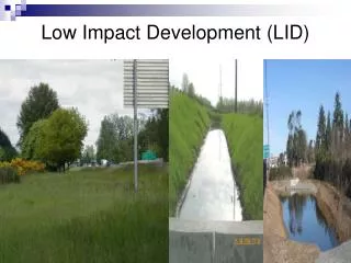
Low Impact Development Opportunities for Bldg 171 • Treat and store water before it reaches drainage inlets • The goal is to reduce overall runoff by 18.6 cfs (EISA) • Challenges • Roof—responsible for nearly 1/3 of peak runoff (5.5 cfs) • Underground utilities • Expansive soils
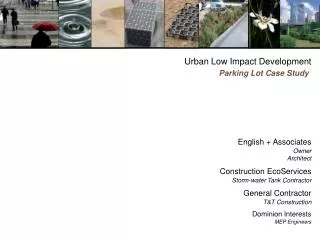
Low Impact Development Opportunities for Bldg 171 • Vegetated strips and rain gardens • Bio-retention • Porous pavement and pavers • Infiltration trench • Sand filter
Low Impact Development Opportunities for Bldg 171 • My recommendations • Combination of vegetated strip and infiltration trench • Utilize existing drainage patterns to capturerunoff • Collect post-treated runoff in an on-site cistern Source: EPA
STORM WATER INLET AT HIGHER ELEVATION OVERFLOW DRAIN DRAINS TO STORM SEWER DRAINAGE INLET CISTERN Source: http://twosweet.bse.vt.edu/Tess/stormwater/images/infil_trench.jpg
Low Impact Development Opportunities for Bldg 171 • Adding storage can decrease overall runoff by 50% • Depression storagein each sub-catchment • Overall runoff down from 140K cubic feet to 68K cubic feet N
Remaining Work • Finish runoff calculations for LID techniques • Calculate LID cost and ROI • Evaluate runoff treatment • TSS • Heavy metals
Time of Concentration Calculations • Assume slope is approximately 0.5% • Calculated peak rainfall intensity = 1.39 in/hr • Assume kinematic viscosity of asphalt = 1.2 x 10⁻⁵ ft2/sec • Manning’s number for asphalt = 0.015 • Path from farthest point in watershed to outlet is 3,225 ft • Calculated unit discharge = 0.1038 ft2/sec • Calculated Reynolds number = 36,400 (Turbulent) • Velocity of overland flow = 1.30 ft/s • Time of Concentration = 41.3 minutes