Download
1 / 26
260 likes | 387 Views
Detector Design and Data Analysis for Heavy Ion Collision Experiments. Peter, Chan Chak Fai SURE 2011 Supervisor: Prof Betty Tsang(NSCL, MSU). National Superconducting Cyclotron Laboratory (NSCL) Michigan State University (MSU). With Prof Betty Tsang and HiRA group. Background.

E N D
Detector Design and Data Analysis for Heavy Ion Collision Experiments Peter, Chan Chak Fai SURE 2011 Supervisor: Prof Betty Tsang(NSCL, MSU)
National Superconducting Cyclotron Laboratory (NSCL)Michigan State University (MSU)
Background • Symmetry Energy Project (SEP) is one of the current projects at NSCL. • Its physics goals include the determination the equation of state of nuclear matter, density dependence of symmetry energy, etc. • Heavy ion collisions (Ca, Sn, etc.) are studied experimentally and with computer simulations. • The project is an international collaboration.
Equation of State Energy in nuclei: Symmetry Energy Term Image from http://www.nscl.msu.edu/~tsang/iso_Texas_11.pdf
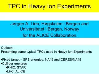
Detector Design • A Time Projection Chamber (TPC) is designed to detect pions and charged particles emitted in heavy ion collisions. • The charged particles produced in heavy ions collision will ionize the gas in the chamber. • The ionized gas is drifted towards the pad plane by electric and magnetic field. • The drift time and the position of the ionized gas can be used to generate the tracks of primary charged particles. • It is designed and made in US and will be installed in RIKEN, Japan. Image from http://www-rnc.lbl.gov/EOS/
Overall Design Lid and electronics Field cage Enclosure Voltage step down
Contributions in TPC design • Use of Computer-Aided Design (CAD) software • Design modification • Model construction • Rotation structure design • Stress calculations
CAD Software used • Autodesk Inventor, a Computer-Aided Design (CAD) software is used for the 3D design of TPC.
Design Modification • Examples of my contributions: • Changed the color of the cooling rod. • Added the copper strips on the corners of the field cage. • Modified the position of the standoff in voltage step down. • Modified the dimension of the enclosure.
Foam Model Making • The foam model of TPC is made and shipped to Japan to ensure it can be placed inside the magnet. • Made together with Jon Barney and Justin Estee. MSU RIKEN
In addition, the TPC should be able to move down the hallways and doors in NSCL.
Rotation Structure Design • The TPC will be assembled upside down since there are wires to be attached to the bottom of top plate. • It has to stand on its side to move down the hallways at NSCL. • One idea is to rotate the TPC around its center of mass:
Stress analysis • The frame structure should be able to support the TPC(~520kg). • The condition of the TPC on its side sitting on a cart is simulated by inventor. • Less than 2mm deformation is observed. • Simulation to rotate the TPC to different orientation is still in progress.
Analysis of Computer Simulated Collision Data • Simulations are done by Hang Liu using the supercomputer in Austin, Texas • Improved Quantum Molecular Dynamics Model (ImQMD) is currently used, the results would be compared to transport theory(BUU) and real collision.s • More than 60000 collision events are generated for each reaction. • The collision under different initial conditions at different energies and impact parameters are simulated: • Examples: - Sn124+Sn124 (sn124s) - Sn124+Sn112 (sn112m) - Sn112+Sn124 (sn124m) - Sn112+Sn112 (sn112s) Visualization of collisions in computer simulation Photo from Y.X. Zhang www.imqmd.com/income/zhang1.pdf
Contributions in Data Analysis • Computation knowledge of Fortran was used • Some observables were analyzed • Neutron-to-proton (n/p) ratio • Tritium-to-helium3 (t/3He) ratio • Ri value
n/p ratio • Example: E70b7x0.7 - beam energy = 70MeV/A - impact parameter = 7fm - stiffness of equation of state of nuclear matter (gamma) = 0.7
After colliding, fragments with lower energy have a higher neutron content, while that with higher energy have a higher proton content. • The graphs of n/p ratio for other reactions and graphs of double ratio were also plotted.
t/3He ratio • t/3He ratio is interesting because neutron is hard to detect in experiment and hence the error in experimental value of n/p ratio is high. • More tritium(t) are produced in lower energy while more 3He are produced in higher energy in general.
The error in this result is larger than that of n/p ratio. • The count number at high energy is small, which produces a relatively high statistical error. • More events will be simulated to reduce the error.
Ri value • Ri is the isospin transport ratio, which is a measure of isospin diffusion. • XAA refers to the neutron-rich system (sn124+sn124), XBB refers to the proton-rich system (sn112+sn112). • If no diffusion, Ri(XAA) = 1; Ri(XBB) = -1. • If isospin equilibrium is reached, Ri(XAB) = Ri(XBA) = 0. • In theory, X is the asymmetry of the fragments. • Two types of Ri: Ri(n,frag) and Ri(zmax>20)
In general, the isospin diffuse more at lower beam energy and lower gamma. Current plan is to compare Ri at more beam energies. • Graphs for comparing different incident energies at fixed impact parameters were made. • The next step is to compare for different impact parameters.
Acknowledgement • Thanks to Betty Tsang, Bill Lynch, Fei Lu, Rebecca Shane, Jon Barney and Justin Estee for all their help! • Thanks to Department of Physics, CUHK for the opportunity of SURE!