Download
1 / 57
570 likes | 652 Views
Place for logos of authors’ institutions. Photonics in Switching Traffic Performance: Bufferless Switches. Carla Raffaelli, University of Bologna, carla.raffaelli@unibo.it Michele Savi, University of Bologna, michele.savi@unibo.it. Motivations.

E N D
Place for logos of authors’ institutions Photonics in SwitchingTraffic Performance:Bufferless Switches Carla Raffaelli, University of Bologna, carla.raffaelli@unibo.it Michele Savi, University of Bologna, michele.savi@unibo.it
Motivations • Tunable Wavelength Converters (TWCs) are expensive components • TWCs should be shared among potential users • Different sharing schemes have been proposed in literature • Share-per-link (input/output) • Share-per-node • Share-per-wavelength • Scheduling algorithms required to manage switch resources
Main assumptions • Full range wavelength converters • Slotted switch operation • Bernoulli balanced input traffic • Optimal scheduling algorithm • Evaluation of optical packet loss probability • Synchronous optical packet switch • N input, N output links • M wavelengths per link M M … … N N M M
Sources of packet loss • Internal blocking • It is a consequence of resource limitation (TWCs, links) inside the switch • Output blocking • It is a consequence of overload on output link in a time slot • Excess packets require the same output link in a time slot • Channel blocking • It is a consequence of overload on a wavelength channel on output link in a time slot • It can be resolved by finding a different channel on the same link to forward the packet • It requires wavelength conversion
Each output link is provided with a dedicated set of R TWCs. The TWCs of the same set can be used only by packets addressed to the related output link. The optical switching fabric can be configured to forward a packet to a link with or without TWCs, depending on traffic conditions. Input packets are first considered for forwarding on the same wavelength on input. If channel contention occurs, wavelength conversion is performed. Not all packets need conversion at the same time slot, so some TWC saving can be achieved Shared per output link architecture M M Space Switching Matrix (non-blocking) Fibre 1 Fibre 1 R Fibre 2 Fibre 2 Fibre N Fibre N
Full: All output channels (M) are equipped with TWCs; Contention is solved; Partial: Only R output channels are equipped with TWCs; Channels without TWCs can only transmit packets on the same input wavelength; Channels with TWCs can convert wavelength to avoid contention; Fully and partially equipped architectures Fibre 1 Fibre 2 Fibre N M R Space Switching Matrix (non-blocking) Fibre 1 Fibre 2 Fibre N
Packet loss probability • Packet loss probability is evaluated on single output fibre “j”; • Packets are lost when output fibre j is congested; • Congestion on output fibre j occurs when: • Case 1: all wavelengths are busy, as well as full wavelength conversion; • Case 2: the number of packets that needs conversion is higher than the number of TWCs;
Loss probability: case 1 • G number of different wavelengths sending packets to output j • M – R channels without TWCs • Case 1: G M – R • M – R packets are transmitted to the output channels without TWC; • All channels without TWC are exploited • R packets are transmitted to the output channels with TWC; • Total packets transmitted: M, remaining packets are lost; • Number of transmitted packets is the same as in the full conversion case; Example: M=6, R=3, G = 4 > M – R; TSlot λ1 λ2 λ3 Out j λ4 λ5 λ6
Loss probability: case 2 • G number of different wavelengths sending packets to output j • M – R channels without TWC • Case 2: G < M – R • G packets are transmitted to the output channels without TWC; • R packets are transmitted to the output channels with TWC; • Total packets transmitted: G + R < M, remaining packets are lost. • Not all channels without TWC can be exploited to transmit packets • loss is higher than in the full wavelength conversion case; Example: M=6, R=3, G = 2 < M–R; TSlot Lost λ1 λ2 λ3 Out j λ4 λ5 λ6
Analytical model: variables • p: arrival probability on a wavelength in a time slot; • Aj: probability of an arrival for output fibre j; • G: number of active wavelengths (with at least one packet for output j) • DG: probability of G active wavelengths; • Gh|G: probability of h arrivals to output j given G active wavelengths • N jl: number of lost packets on output j in a time slot; • N jo: number of packets offered to output j in a time slot; • Pl: packet loss probability.
Expression of packet loss probability Pl • Pl can be expressed in relation to the generic output j by definition as the ratio between the averages of Njl and Njo : • Under the assumption of uniform traffic the average number of packets offered to output j in a time slot, Njo, is given by • and the average number of lost packets on output j in a time slot, Njl, is given by • where G = 1..M
Average number Njl of lost packets on output j • Njl is calculated by taking into account the contributions of case 1 and case 2 • Expressions of Gh|Gfor G=0 and G=1 where represents the normalizing factor representing the probability of h>0
Recursive formula for Gh|G • When • When
DG is the probability that G different input wavelengths send packets to output fibre j; Γh|G is the probability of h packet arrivals, given that G different input wavelengths send packets to output fibre j; Packet Loss Probability
Packet loss probability: special cases • Full wavelength conversion • No wavelength conversion
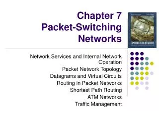
The results show the minimum number of wavelength converters needed to achieve the same loss of full wavelength conversion; Simulation set-up: N=8, M=16; Packet loss probability as a function of the number of TWCs is evaluated in according to different values of load per wavelength; Packet loss probability
Simulation set-up: M=16, P=0.7; Packet loss probability as a function of the number of TWCs is evaluated in according to different switch size; Packet loss probability is slightly depend on switch size; Packet loss probability
Simulation set-up: N=8, N=16; Percentage of TWCs needed to maintain loss probability increase smaller than 10% respect to full wavelength conversion; Percentage of wavelength converters • Respect to the full wavelength conversion case (100%), the saving of TWCs is very remarkable;
Share-per-node architecture M M M M IN 1 OUT 1 1 R Strictly Non-Blocking (SNB) Space Switching Matrix OUT N IN N • All TWC (R) are grouped in the same set • The TWC are shared by all input channels • Only the packets that require conversion are sent to TWCs • The converted packets are then sent to the appropriate output link by a further optical switching stage • The TWC saving is here paid with a complexity increment of the optical switching fabrics
Fully and partially equipped architectures • Full: • In this case R=MN; • All input channels can exploit TWC; • Contention is solved; • Partial: • Only R < MN TWCs are available to solve contention; • Packets that don’t need conversion are sent on the same input wavelength by means of optical channels without TWC; • Packets that need conversion are sent on TWC bank and exploit wavelength conversion to avoid contention; • Some packets can be blocked at the TWC bank due to the lack of TWCs;
Packet loss probability • Packet loss probability is evaluated as the probability that a tagged packet directed to output fibre “j” is discarded; • The tagged packet is lost when: • Case 1: output fibre “j” is congested and the tagged packet is not among ones chosen for transmission; • Congestion on output fibre “j” occurs when all wavelengths are busy; • Case 2: total number of packets that needs conversion exceeds number of TWCs in the bank and the tagged packet is not a chosen one for conversion (and transmission);
5 packet arrivals directed to output fibre 1 in a time slot; First, one packet from each different wavelength is sent without conversion; Then, other packets are sent exploiting wavelength conversion; If destination output fibre is congested, packet is lost; If destination output fibre is congested, packet is not sent on TWC bank; TWC can be exploited from packets that compete for another output fibre; Case 1: packet lost because output fibre is congested ! LOST • N=2 input/output fibres; • M=4 wavelengths per fibre; • R=2 TWCs; 1 Out 1 In 1 1 1 1 Out 2 In 2 1
4 packet arrivals directed to output fibre 1 in a time slot; First, one packet from each different wavelength is sent without conversion; Then, other packets are sent exploiting wavelength conversion; If no TWC are available, packet is lost even if there are available wavelengths on target output fibre; Case 2: packet lost due to the lack of TWCs ! LOST • N=2 input/output fibres; • M=4 wavelengths per fibre; • R=1 TWC; 1 Out 1 In 1 1 1 Out 2 In 2 1
Scheduling algorithm • Ideal shared per node architecture requires proper scheduling algorithm to solve contention situation; • OPTIMAL scheduling algorithm: in this context an algorithm is optimal if it allows to forward the maximum number of packets; • To this end, packets that don’t require conversion must be forwarded in optical channels without TWC, other packets require conversion so that are sent to TWC bank; • Here an optimal scheduling algorithm composed by 2 steps executed in each time slot is presented
Step 1: input fibres are sequentially scanned and packets carried by same wavelength and directed to same output fibre are grouped; Step 2: to assure fairness, output fibres are served randomly: one packet (randomly chosen) from each group related to target output fibre are sent without conversion: It is assured that maximum number of packets are sent without conversion; other packets (randomly chosen) from groups related to target output fibre are sent exploiting TWCs; packet loss occurs when more than R packets must be converted (or output fibre is congested); Scheduling algorithm: description Group 1 - out 2, 3 packets Group 1 - out 1, 1 packet Group 2 - out 2, no packet Group 2 - out 1, 2 packets Group 3 - out 1, no packet Group 3 - out 2, 1 packet Group 4 - out 1, no packet Group 4 - out 2, 2 packets 1 In 1 2 In 2 1 2 2 In 3 2 2 1 In 4 2
Analitycal model: hypothesis & variables Hypothesis: • Synchronous environment; • Packet length equal to time slot duration; • Bernoulli independent arrivals on input wavelengths; • Packet arrivals are addressed to the output fibres with same probability 1/N; Variables: • p: probability of arrival on a wavelength in a time slot; • Pu: probability that output fibre “j” is congested and tagget packet is not chosen for transmission (external packet block); • Pb: probability that tagged packet is blocked on its wavelength on output fibre “j”; • Awc: traffic offered to TWC(s) bank from each wavelength; • Pbwc: probability that tagged packet is lost because TWCs unavailability; • Ploss: packet loss probability;
Expression of packet loss probability Ploss • First term represent external block, Pu; • Second term represent joint probability that: • packet is sent on TWC bank, given by product of: • Pb (packet is blocked on its wavelength); • 1-Pu/Pb (packet is not blocked on target output fibre “j” given that it is blocked on its wavelength); • packet is lost because no TWC is available;
Expression of Pu • Pu is evaluated on output fibre “j”; • Pu is calculated assuming infinite wavelength conversion capability; • There are up to MN packet arrivals directed to output fibre “j”, only M are sent; • Packet loss occurs when there are h > M arrivals and tagged packet is blocked; • Probability of h arrivals is evaluated as probability of h – 1 arrivals on MN – 1 input wavelengths other than the tagged;
Expression of Pb • Pb is evaluated considering a generic wavelength “k” on output fibre “j”; • There are up to N packet arrivals carried by wavelength “k” and directed to output fibre “j;” • Block on wavelength “k” occurs when there are h > 1 packet arrivals and the tagged is not the one forwarded without conversion; • Probability of h arrivals is evaluated as probability of h – 1 arrivals on wavelength “k” in the N – 1 input fibres other than the tagged;
Traffic on TWC bank • It is necessary to evaluate traffic offered to TWC bank from each output wavelength; • Probability that a packet is sent to TWC bank: • Load per input wavelength: p; • Traffic on TWC bank:
Expression of Pbwc • Assuming Bernoulli independent arrivals on input of bank, there are up to MN possible arrivals, each one with probability Awc; • There are R < MN TWC in the bank; • Packet loss occurs when there are h > R arrivals and the tagged packet is blocked; • Probability of h arrivals is evaluated as probability of h – 1 arrivals on MN – 1 output wavelengths other than the tagged;
Packet loss probability: special cases • Full wavelength conversion (R=MN): • no packet loss on TWC bank; Pbwc=0 Ploss=Pu; • No wavelength conversion (R=0): • packets that require conversion are lost; Pbwc=1 Ploss=Pu+Pb(1-Pu/Pb)Pbwc=Pb;
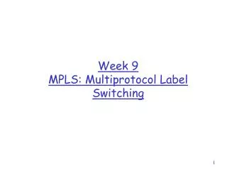
Simulation set-up: N=16, M=8; Packet loss probability as a function of the number of TWCs is evaluated in according to different values of load per wavelength; SPN architecture allows to save TWCs; Packet loss is high due to the lack of optical buffer; Packet loss probability N=16, M=8 1 0.1 0.01 0.001 0.0001 Packet Loss Probability 1e-005 1e-006 p=0.9 - A 1e-007 p=0.9 - S p=0.7 - A p=0.7 - S 1e-008 p=0.5 - A p=0.5 - S p=0.3 - A 1e-009 p=0.3 - S p=0.1 - A p=0.1 - S 1e-010 0 10 20 30 40 50 R
Simulation set-up: N=16, M=8; Minimum number of TWCs needed to achieve same performance as full wavelength conversion (a) and to maintain loss increase lower than 1% (b); With this set-up saving is very relevant; TWC saving
Packet loss probability N=16 N=16 1 1 0.1 0.1 0.01 0.01 0.001 0.001 Packet Loss Probability Packet Loss Probability 0.0001 0.0001 1e-005 p=0.9 - M=8 p=0.9 - M=8 p=0.9 - M=16 p=0.9 - M=16 1e-006 p=0.9 - M=32 p=0.9 - M=32 1e-005 p=0.5 - M=8 p=0.5 - M=8 p=0.5 - M=16 p=0.5 - M=16 1e-007 p=0.5 - M=32 p=0.5 - M=32 1e-006 0 0.2 0.4 0.6 0.8 1 0 100 150 200 50 R % TWCs • Set-up: N=16, M=8-16-32; • Packet loss probability as a function of number of TWCs varying number of wavelengths per fibre and load; • When number of wavelengths increases, packet loss decreases;
Analytical model proposed for SPN architecture is very flexible; • It can be used to evaluate packet loss in some particular cases; • Here, the analytical model is used to evaluate performance of shared per wavelength switch.
The TWCs in a node are shared per wavelength; B TWCs are shared among packets carried by the same wavelength; Each wavelength have a dedicated pool of B TWCs; Fixed-input/tunable output TWCs can be used; Total amount of MB TWCs; Same switching fabrics as in the SPN, their size depends on the number of TWCs (MB). Shared per wavelength architecture M M M M IN 1 OUT 1 1 1 R M OUT N IN N Strictly Non-Blocking (SNB) Space Switching Matrix
Full and partial conversion • Full wavelength conversion: • In this case B=N TWCs per wavelength (NM in total); • All input channels can exploit a given TWC; • Contention is solved; • Partial wavelength conversion: • Only R < N TWCs per wavelength are available to solve contention; • Packets that don’t need conversion are sent on the same input wavelength by means of optical channels without TWC; • Packets that need conversion are sent to the proper TWC pool and exploit wavelength conversion to avoid contention; • Some packets can be blocked at the TWC pool due to the lack of TWCs;
Scheduling algorithm • Similar to the one for the SPN switch • Step 1: packets carried by the same wavelength and directed to the same output fibre are grouped; • Step 2: one packet, randomly chosen, from each group is sent without conversion • Maximum number of packets forwarded without conversion; • Step 3: • packets exceeding the number of wavelengths in the destination output fibre are lost due to output blocking • up to B packets on the same wavelength (max N) can exploit the B TWCs dedicated to this wavelength and are forwarded with conversion • exceeding packets are lost due to the lack of TWCs
Scheduling algorithm: example 1, out 1 N=3, M=4 OUT 1 RANDOM OUT 1 3, out 1 OUT 1 OUT 3 2, out 2 OUT 2 OUT 3 OUT 1 4, out 3 OUT 3 FASE 2: O(NM) FASE 1: O(NM) FASE 3: O(N+MB)
Analitycal model: hypothesis & variables Hypothesis: • Synchronous environment; • Packet length equal to time slot duration; • Bernoulli independent arrivals on input wavelengths; • Packet arrivals are addressed to the output fibres with same probability 1/N; Variables: • p: probability of arrival on a wavelength in a time slot; • Pu: probability that output fibre “j” is congested and tagget packet is not chosen for transmission (external packet block); • Pb: probability that tagged packet is blocked on its wavelength on output fibre “j”; • Awc: traffic offered to TWC(s) bank from each wavelength; • Pbwc: probability that tagged packet is lost because TWCs unavailability; • Ploss: packet loss probability;
Up to N packets contending for B TWCs The analytical model proposed for the SPN can be used to evaluate performance of this architecture with a few changes: packets carried by same wavelength contend among each other for only B TWCs; Considering SPW switch, only Pbwc has to be adapted to new contention situation, the rest of the model is identical: SPW switch: packet loss probability
Simulation set-up: N=16, M=8; Packet loss probability as a function of the number of TWC blocks is evaluated in according to different values of load per wavelength; Multistage architecture allows to save TWC blocks; Packet loss is high due to the lack of optical buffer; SPW switch: packet loss probability
Simulation set-up: N=16, M=8; Minimum number of TWC blocks needed to achieve same performance as full wavelength conversion (a) and to maintain loss increase lower than 1% (b); Multistage architecture: TWCs saving
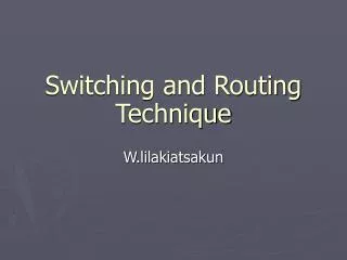
Simulations obtained by applying the proposed scheduling algorithm Packet loss probability as a function of the number of TWCs dedicated to each wavelength (B) Same performance as fully equipped architecture with a limited number of TWCs The model overestimates the packet loss when the number of wavelengths per fibre is high (low loss due to output blocking) Due to the independence hypothesis made for the arrival at the TWC pool SPW: Simulation vs Analysis N=20, M=50 N=16, M=8 1 1 0.1 0.1 0.01 Packet Loss Probability 0.01 Packet Loss Probability 0.001 0.0001 0.001 0.6 - S 0.3 - A 1e-005 0.6 - A 0.3 - S 0.7 - S 0.0001 0.7 - A 1e-006 0 2 4 6 8 10 0 5 10 15 20 B B 0.7 - S 0.7 - A N=20, M=100 1 0.1 0.01 Packet Loss Probability 0.001 0.0001 1e-005 1e-006 0 5 10 15 20 B
Example: multi-stage S-λ-S architecture: practical implementation of the SPW architecture
All-optical multistage architecture: achieved by all-optical components like Erbium-Doped Fiber Amplifiers (EDFAs), ON/OFF gates (SOAs), couplers/splitters and TWCs; 3 stages: first and third stage are identical (broadcast and select stage); second stage is conversion stage; Architecture fully equipped with TWCs: full wavelength conversion is achieved contention is solve, no internal block; Example of application: multistage architecture
Modified architecture to achieve partial wavelength conversion: some blocks of TWC in the conversion stage are replaced by simple optical fibres; only B TWC blocks; N – B optical fibres; architecture with TWCs shared per node is achieved; performance must be evaluated in relation to the number of TWCs; Multistage architecture: sharing TWCs
Multistage architecture: space equivalent • The space equivalent is composed by 3 stages • first and third stages are identical, composed by M cross-bars with size NxN, each one representing wavelength contention; • second stage represents conversion stage: • in fully equipped architecture, it is composed by N cross-bars with size MxM (a single cross-bar represents a cascade of an array of M TWCs and a N:1 coupler); • in partial wavelength conversion architecture it is composed by only B cross-bars with size MxM and N-B groups of M simple optical links;
In this architecture, each different wavelength (0 in the figure) can exploit N – B simple optical links and B TWCs, placed each one in different TWC blocks; Groups of simple optical links are N – B, when the number of TWC blocks B increases, the number of optical links decreases; Multistage architecture: particular organization of TWCs