Download
1 / 25
250 likes | 373 Views
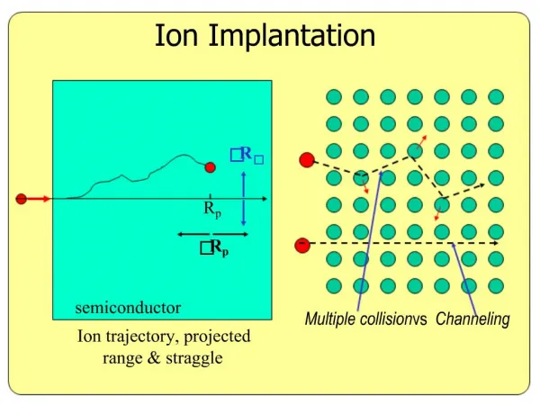
Multiscale Approach for the Analysis of Channeling Profile Measurements of Ion Implantation Damage. G. Hobler, G. Otto, D. Kovac L. Palmetshofer 1 , K. Mayerhofer², K. Piplits² 1 Inst. Semiconductor and Solid State Physics, Univ. Linz ² Inst. Chem. Technol. and Analytics, TU Vienna.

E N D
Multiscale Approach for the Analysis of Channeling Profile Measurements of Ion Implantation Damage G. Hobler, G. Otto, D. KovacL. Palmetshofer1,K. Mayerhofer², K. Piplits² 1 Inst. Semiconductor and Solid State Physics, Univ. Linz² Inst. Chem. Technol. and Analytics, TU Vienna Institute of Solid-State Electronics
Damage Models in BC Simulations • Traditional model: • defect positions: generated statistically • atom positions: random interstitial model • dynamic annealing: „recombination factor“ • Proposed model: • defect positions: trace each defect during the whole simulation • atom positions: take from ab-initio simulations • dynamic annealing: kinetic lattice Monte Carlo simulation (kLMC) after each collision cascade
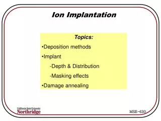
Overview • Introduction • BC-kLMC approach • Application to channeling profile measurement (CPM) experiments
Damage Measurements Channeling profile RBS
Channeling Implantations • Fit dose dependence of channeling implantation profiles recombination factor frec=0.125 Nsat=41021cm-2 (G.Hobler et al., J. Vac. Sci. Technol B14 (1) 272, 1996)
Channeling Profile Measurements • Measure pre-existing crystal damage with a low-dose channeling implant (M. Giles et al., MRS Symp. Proc. 469, 253, 1997)
The Role of Dynamic Annealing in Si • Temperaturedependence of implant damage: (J.E. Westmoreland et al., Appl. Phys. Lett. 15, 308, 1969)
The Role of Dynamic Annealing in Si • Dose-rate dependence of implant damage: 70µA/cm² 0.14µA/cm² T=300K (O.W. Holland et al., Rad. Eff. 90, 127, 1985)
Overview • Introduction • BC-kLMC approach • Application to channeling profile measurement (CPM) experiments
Coupled BC-kLMC Approach • Traditional approach: • BUT: type and amount of defects influence BC trajectories (dechanneling) point defects BC loop over cascades 1 cascade kLMC point defects + clusters
Coupled BC-kLMC Approach • Proposed new approach: defects atom positions for each defect loop over cascades BC old defects + new point defects kLMC point defects + clusters
Details of kLMC • Each defect is associated with one or more lattice sites • Defects: Vn, In (n=1,2,3,...) • Events: • Diffusion hops (I, V) • Reactions of defects located within capture radius Vn+V Vn+1 Vn+I Vn-1 In+I In+1 In+V In-1 • Parameters: • DV=310-13 cm²/s DI=6.3510-17 cm²/s • (Capture radii)
Details of kLMC • „Old“ defects: restricted to column(periodic boundaryconditions) • „New“ defects: anywhere • Interaction between „new“ and „old“ defects: Using periodicity of „old“ defects
Details of BC • Read defects from kLMC (columnar domain) • Use periodicity to generate defects around projectile • Atom positions from ab-initio calculations (VASP) • defect structure • strain around defect • All defects composed of individual I and V (currently)
Overview • Introduction • BC-kLMC approach • Application to channeling profile measurement (CPM) experiments
CPM Experiments • Damage implant: N, 30 keV, 31014 cm-², 10° tilt • CPM implant: B, 30 keV, 1013 cm-2, 0° tilt (110)-Si shield
CPM Experiments • Results:
CPM Simulation Results • Simulation results without strain:
CPM Simulation Results • Strain from vacancies:
CPM Simulation Results • Strain from interstitials:
What is wrong? • Defects: Vn, In (n=1,2,3,...) • Events: • Diffusion hops (I, V) • Reactions of defects located within capture radius Vn+V Vn+1 Vn+I Vn-1 In+I In+1 In+V In-1 • Parameters: • DV=310-13 cm²/s DI=6.3510-17 cm²/s • (Capture radii) • Lack of amorphous pockets?
What is wrong? • Defects: Vn, In (n=1,2,3,...) • Events: • Diffusion hops (I, V) • Reactions of defects located within capture radius Vn+V Vn+1 Vn+I Vn-1 In+I In+1 In+V In-1 • Parameters: • DV=310-13 cm²/s DI=6.3510-17 cm²/s • (Capture radii) • Lack of amorphous pockets? NO • Approximate treatment of I-Clusters?
I3 I2 I I4a I4b What is wrong? • I-Clusters: • Similar study on RBS-C: Efficiency of I2, I3, I4 within 40% of split-110 interstitial (G. Lulli et al., Phys. Rev. B69, 165216, 2004)
What is wrong? • Defects: Vn, In (n=1,2,3,...) • Events: • Diffusion hops (I, V) • Reactions of defects located within capture radius Vn+V Vn+1 Vn+I Vn-1 In+I In+1 In+V In-1 • Parameters: • DV=310-13 cm²/s DI=6.3510-17 cm²/s • (Capture radii) • Lack of amorphous pockets? NO • Approximate treatment of I-Clusters? Probably not • Attraction of I+Vn, V+Inand/or Repulsion of I+In, V+Vn
Conclusions • New approach for implant damage simulations • coupled BC and kLMC • atom positions from ab-initio • Consistent simulation of both defect generation and analysis • Simulations yield too much damage need to use • interaction radii to favor recombination and/or • reaction barriers to impede clustering