Download
1 / 38
380 likes | 482 Views
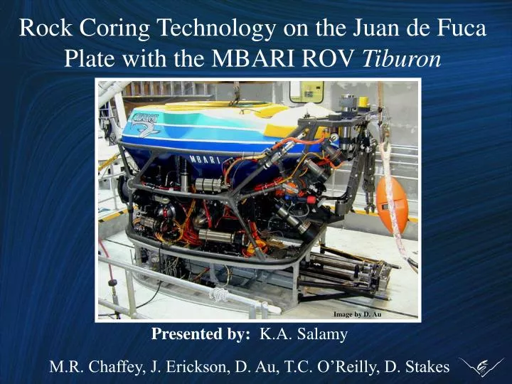
Rock Coring Technology on the Juan de Fuca Plate with the MBARI ROV Tiburon. Image by D. Au. Presented by: K.A. Salamy M.R. Chaffey, J. Erickson, D. Au, T.C. O’Reilly, D. Stakes. Topics. Brief history of M ultiple-barrel C oring S ystem (MCS) on underwater science platforms.

E N D
Rock Coring Technology on the Juan de Fuca Plate with the MBARI ROV Tiburon Image by D. Au Presented by: K.A. Salamy M.R. Chaffey, J. Erickson, D. Au, T.C. O’Reilly, D. Stakes
Topics • Brief history of Multiple-barrel Coring System • (MCS) on underwater science platforms • Recent Adaptation of the MCS to the ROV • Tiburon - Project Requirements • - System Design Modifications • MBARI Summer 2000 Coring Highlights - Juan de Fuca Plate
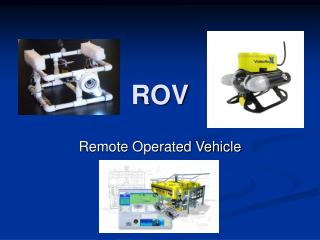
ALVIN Submersible (1991, 1996) ROV ROPOS (1998) ROV Ventana (1992-1999)
Project Purpose - Increased depth capabilities - 4000 meters - Wider geographical sampling coverage • Adapt the MCS to Tiburon for marine geological sampling
Direct Transfer of Existing Technology • Minimum changes to Ventana design • Main modifications/additions to: • - MCS control system • - Software Architecture (real-time feedback) • - New toolsled frame • Summer 2000 “hard” deadline date
Functional Requirements • 4000-meter MCS operational depth • Explosive cutter software and hardware must operate safely and reliably • Tiburon MCS performance must equal • existing design • - Sufficient power to core • - Maintain position while coring • - Similar coring rates (0.5m / hr) • - Horizontally-level cores
Design Issues • Power for coring on Tiburon - 15kW • - Hydraulic power • - Thrust for Weight-On-Bit • - Station-keeping abilities • Re-use versus Redesign of existing system - Sensing and control - Explosive cutter circuit - Software architecture
System Design Requirements • Total power to operate MCS (< 5.3 kW) • Minimum drillstring stall torque ~ 130 Nm • RPM variable from 0 to +/- 400 RPM • Provide 220 lbs Weight-On-Bit • Use standard Tiburon toolsled frame
Weight-On-Bit Analysis 138 lbs. 270 lbs. 270 lbs.
Data-CONcentrator (DCON) for Sensing and Control • Versatile hardware development • - Multiple 2A current digital outputs for • hydraulic valve control • - Analog inputs for reading sensors • - Analog outputs for hydraulic servo valves • - Digital outputs for controlling cutter circuit • - Digital inputs for monitoring cutter status • - Ground fault, humidity and water alarms • Efficient software development
Resulting Tiburon MCS Design Image by J. Erickson
Explosive Cutter Requirements • Shears drill string when • Commanded by pilot and below 150 meters or • System armed and power lost for one hour and below 150 meters • Does NOTfire otherwise!
Explosive Cutter Firing Sequence Pilot commands “fire” Power plug inserted on deck Pressure switch closes Pilot commands “arm” FAST FIRE POWER PLUG 150 METERS ARMED Power fail fire DELAYED FIRE
Disarmed Armed Fast-firing “Disarm” button pushed orpressure switch opens “Disarm” button pushed orpressure switch opens “Arm” button pushed and password entered “Disarm” button pushed orpressure switch opens Delayed- firing DCON power ON “Fast-fire” button pushed and password entered DCON power OFF DCON power OFF “Fast-fire” button pushed and password entered * 1 hour elapsed 15 seconds elapsed Explosive Cutter State Diagram Fired * Allowable if cutter mistakenly believes IBC power is OFF Software-initiated transition Hardware-initiated transition
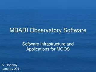
Application Software Requirements • Graphical user interface (GUI) • - Display and control MCS state • Accept and process user commands • Sample and distribute sensor telemetry • Sense and report DCON “events”
Western Flyer optical fiber serial lines Sonar DCON Main vehicle computer Camera DCON MCS DCON Tiburon
DCON micro- processor Main vehicle computer DataManager items GUI workstation alarms, events Main task Sampler sensor telemetry DCON 196 CPU Command monitor commands DCON application components - Object Oriented Techniques provide rapid software development that is robust, efficient and maintainable.
DCON micro- processor Main vehicle computer DataManager items GUI workstation alarms, events Main task Sampler sensor telemetry DCON 196 CPU Command monitor command commands telemetry • User pushes Drill button on GUI to begin coring; GUI writes DataManager “commands” item to “ON”
DCON micro- processor Main vehicle computer DataManager items GUI workstation alarms, events Main task Sampler sensor telemetry DCON 196 CPU Command monitor command commands telemetry • Command monitor task on main vehicle computer detects change in “commands” DataManager item • Reads value, checks for valid requested state
DCON micro- processor Main vehicle computer DataManager items GUI workstation alarms, events Main task serial Sampler sensor telemetry DCON 196 CPU Command monitor command commands telemetry • Command monitor task writes “switch on” serial command to hydraulic valve switch card on DCON • Switch closes
DCON micro- processor Main vehicle computer DataManager items GUI workstation alarms, events Main task serial Sampler sensor telemetry DCON 196 CPU Command monitor command commands telemetry • Sampler task periodically reads card state via serial line
DCON micro- processor Main vehicle computer DataManager items GUI workstation alarms, events Main task serial Sampler sensor telemetry DCON 196 CPU Command monitor command commands telemetry • Sampler task updates DataManager item to reflect new switch state
DCON micro- processor Main vehicle computer DataManager items GUI workstation alarms, events Main task serial Sampler sensor telemetry DCON 196 CPU Command monitor command commands telemetry • GUI detects changed value of “switch state” item, updates display
DCON micro- processor Main vehicle computer DataManager items GUI workstation alarms, events Main task serial Sampler sensor telemetry DCON 196 CPU Command monitor command commands telemetry • Main task monitors the DCON for unsolicited events (e.g., alarms and events), propagates the events through DataManager, and updates the GUI display
CLEFT DRILL CORE SAMPLE LOCATIONS
Science Benefits • MCS used on 7 geology dives - 11 cores acquired - Similar coring rates - High resolution sampling • All cores deeper than 2000 meters.- Deepest at 3,160 meters. • Coreholes horizontally-level • - Future instrument emplacements.
Additional Design Benefits • Fast integration of MCS on Tiburon- 1 hour toolsled change-out • Consistent use of proven applications • - Interchangeable toolsleds • - Modular DCON-based electrical architecture • - Application framework software architecture • Efficient implementation of new systems- Ensures pilot familiarity (command / controls)- Minimizes pilot training time