Download
1 / 26
260 likes | 376 Views
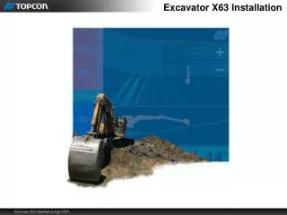
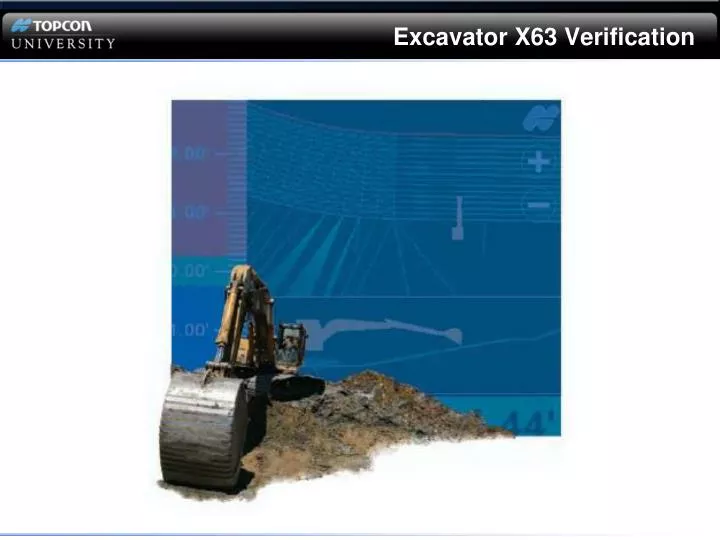
Excavator X63 Verification. This Webinar is LISTEN only. QUESTIONS?. Questions will be answered in writing at the end of the Webinar. Last Week Webinar Update. Correction on installation information No software termination for bucket sensor Hardware termination on bucket sensor

E N D
This Webinar is LISTEN only QUESTIONS? Questions will be answered in writing at the end of the Webinar.
Last Week Webinar Update • Correction on installation information • No software termination for bucket sensor • Hardware termination on bucket sensor • CAN filter for GX60 Bucket Termination 7010-0916 CAN Isolator
Reference Material 7010-0697 Excel Verification
Excavator X63 Verification Webinar September 11th, 2009 • Verification Excel Work Sheets • TS-1 Calibration Verification • MC-A1 Position Verification
Verification No Verification (Rotation error) Not critical Graphics only
TS-1 Calibration and Implement Length Verification • Start 3DMC and enter simulation mode.
TS-1 Calibration and Implement Length Verification • In Simulation • Set Level String • Match Elevation
Antenna Measurements (using GPS) • Compare GPS measured distance to the physical measured distance to adjust Main/Aux Antenna position • RTK Solution (Single point localization ) • Planner Surface • Rover with Pocket 3D
Verifying Main Antenna to Boom Length • Position the machine directly North • Mark bucket location and record Northing value • Rotate 180o • Position the machine directly North • Mark bucket location and record Northing value
Verifying Main Antenna to Boom Length • Subtract the two Northing values to get a GPS distance • 15.50’ • Using a tape or Rover measure the actual distance • 15.30’ • Subtract the two values and divide by 2 • (15.50-15.30 = .20)/2 = .10 • If the GPS measured(Northing) value is larger shorten the length in 3D-MC • If the tape measured value is larger lengthen the length in 3D-MC
Verifying Aux Antenna to Boom Length • Rotational Heading
Verifying Aux Antenna to Boom Length • Position the machine directly North • Curl the bucket in and record: • 3DMC Easting of a bucket corner (position screen) • Easting with Rover and Pocket 3D • Extend the bucket to its fullest and record: • 3DMC Easting of the same corner (position screen) • Easting with Rover and Pocket 3D
Verifying Aux Antenna to Boom Length • Curled bucket Easting: • 3DMC 520.35 • Rover 520.38 • Extended bucket Easting: • 3DMC 520.36 • Rover 520.51 • The difference in curled position • 520.38 - 520.35 = .03 • The difference in extended position • 520.51 – 520.36 = .15 • Measured distance from curled to extended • 20’
Verifying Aux Antenna to Boom Length • Determine the Aux antenna correction amount using this formula: • A(Distance Between Antennas) C(Ext Easting – D (Curl Easting) • X B (Curl To Ext Distance) = 7.5 .15 - .03 X 20 = X=.045 • Curled bucket Easting: • 3DMC 520.35 • Rover 520.38 • Extended bucket Easting: • 3DMC 520.36 • Rover 520.51 Rover Easting's larger (decrease) 3DMC Easting’s larger (Increase)
Verifying Main Antenna Offset • Position the machine directly North • Curl the bucket in and record: • 3DMC Easting of a bucket corner (position screen) • Easting with Rover and Pocket 3D • Extend the bucket to its fullest and record: • 3DMC Easting of the same bucket corner (position screen) • Easting with Rover and Pocket 3D
Verifying Main Antenna Offset • Curled bucket Easting: • 3DMC 520.35 • Rover 520.38 • Extended bucket Easting: • 3DMC 520.48 • Rover 520.51 • The difference in curled position • 520.38 - 520.35 = .03 • The difference in extended position • 520.51 – 520.48 = .03 • If Rover Easting's are larger (increase) • If 3DMC Easting’s are larger (decrease)
Verifying Main Antenna Height • Record several 3DMC bucket elevations and corresponding survey rover elevations • Subtract the elevations and find the average • If 3DMC elevations are higher than the rover increase the antenna height • If 3DMC elevations are lower than the rover decrease the antenna height.
Elevation/Position Errors • Wedge errors or Inconsistent elevation errors • Perform Elevation Accuracy Verification to check machine and sensor calibration • Overall bias between machine and rover • Perform Main Antenna Height Verification • Northing Errors: • Perform Main Antenna to Boom Length Verification • Rotational Errors: (curled to extended) • Perform Aux Antenna to Boom Length Verification • Easting Errors: • Perform Main Antenna Offset Verification
Address to download all TU-Live Webinars: ftp://TUlive+topconuniversity.com:tulive@ftp.topconuniversity.com/ Recorded Webinar PP Presentation; Introduction to Paver System Five Webinar Q & A Additional requests for TU staff: Email: training@topcon.com Questions?