Download
1 / 43
430 likes | 535 Views
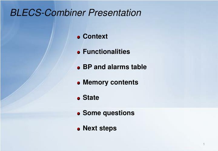
BLECS-Combiner Presentation. Context Functionalities BP and alarms table Memory contents State Some questions Next steps. BLECS-Combiner Context. IC Ionization chamber BLECF BLM data acquisition card Current to Frequency BLETC BLM data processing and Threshold Comparator

E N D
BLECS-Combiner Presentation • Context • Functionalities • BP and alarms table • Memory contents • State • Some questions • Next steps
BLECS-Combiner Context IC Ionization chamber BLECF BLM data acquisition card Current to Frequency BLETC BLM data processing and Threshold Comparator BLECS BLM Combiner and Survey CIBUS Controls Interlocks Beam User Single HV High Voltage power supply BLETCN°1 BLETC N°16 BLECS Create 1 BLECF IC BLECF IC BLETC N°16 BLECS • 1 to 4 crate connected in series with the BLECS • Same connection between BLECS and between BLECS and CIBUS • Last BLECS control the HV but all can read the HV voltage BLETCN°1 BLECF Create 2 IC BLECF IC BLETCN°1 BLETC N°16 LastBLECS BLECF Create n IC BLECF IC CIBUS Unmascable Beam Permit CIBUS Mascable Beam Permit HV1 + HV2
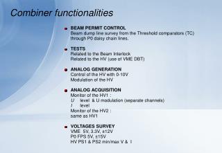
BLECS-Combiner Functionalities • BEAM PERMIT TRANSMISSIONBeam Permit lines transmission from the Threshold comparators (TC) to the CIBU (Interlock network), tagging. • BEAM ENERGY CONVERSION & DISTRIBUTIONReceive the energy from the CTRV, converse it in 5 bits value and distribute it to the whole create. • ANALOG GENERATION AND ACQUISITIONControl and Monitoring of the high voltage (HV) for the ionization chambers • TESTSRelated to the Beam InterlockRelated to the Beam EnergyRelated to the HV • VOLTAGES SURVEYHV and low voltage with level comparators
BLECS-Combiner Functionalities BEAM PERMIT LINE CONTROL OFF ON Q Q Lines from BLECS (Up) Lines from FPGA (frequency > 1MHz) Transient voltage suppressors @ BLECS output ?
BLECS-Combiner Functionalities BEAM PERMIT LINE CONTROL BLECS Beam permit output spec • Uout(ON) = 5V • Uout(OFF) = -5V • ±Iomax = 25 mA
BLECS-Combiner Functionalities Beam permit related parts FPGA Beam Permit from TC (M) Beam Permitdecision unit Beam Permit to CIBU (MA) Beam Permit from TC (U) Beam Permit to CIBU (MB) Beam Permit from BLECS (MA) Beam Permit to CIBU (UA) Beam Permit from BLECS (MB) Beam Permit to CIBU (UB) Beam Permit from BLECS (UA) Post-mortem and Login Beam Permit from BLECS (UB) Time Stamps (orbit counter) Test Failure Clock from BOBR Beam Energy Failure Dump table
BLECS-Combiner Functionalities Beam permit related parts BLETC Power Supplies Comparators Logic Beam Dump (M & UM) Beam permitdecision unit P0 Connector Beam Energy (Serial) Tests CISV Beam Energy (Serial) Post-mortem BLECS Beam permit P2 Connector Beam info BLECS or CIBUS FPGA Beam permit Comparators HV1 12 lines HV2 VME PS 4x P0 PS 3x
BLETC P0 Connector Beam Energy (Serial) Energy conversion & add informations CTRV P2 Connector Beam Energy (Serial) FPGA BLECS-Combiner Functionalities Beam Energy related parts • Serial reception (redundant A and B) • Counters: Frame, CRC error, Lost of FrameToggle bit • Translation 16 bits to 5bits, hard coded conversion table • Substitution of the original value by any value (in test mode only) • Additional information (tests commands for the TC) on the reminded free bits (see tests functionalities section further) • Serial transmission to up to 16 TC receivers in parallel Dump table
BLECS-Combiner Functionalities Beam Energy Dump table
BLECS-Combiner Functionalities Beam Energy test setup on BA5 2 21 20 6 5 CPU CTRV BLETC BLECS CTG BLETC BLETC P0 P0 P0 P0 CTRP 3 4 P2 P2 1
16 bits DAC8532 Offset Analog SUM RCFilter Zenner 6.8V FPGA Pot digitally Controlled (8 bits steps) Modulation Close to the connector (P2) FPGA BLECS-Combiner Functionalities ANALOG GENERATION To HV supply The high voltage power supplies for the ionization chambers are controlled by analog signals 0-10V. There is an analog sum done between the 2 outputs of the DAC, the modulation signal is attenuated with a potentiometer digitally controlled. BLECS-Combiner-Schematics-Rev1
BLECS-Combiner Functionalities ANALOG ACQUISITION ADC Buffer LP Filter From the HV voltage monitoring Instrumentation amplifier FPGA Offset compensation Digital pot. FPGA GAIN Digital pot. LP Filter From the HV current monitor Buffer The high voltage power supplies have analog output monitors to view the voltage and current levels, there is 1 channel for the current and 2 channels of digitalization for the voltage (offset and low frequency modulation) Dump table BLECS-Combiner-Schematics-Rev1
BLECS-Combiner Functionalities: Tests TESTSRelated to the Beam InterlockRelated to the Beam Energy Related to the HV The tests are triggered by the CPU (Sequencer?) and are activated by the BLECS only if the Beam info indicate that there is no beam permit. For some tests, the result can only be computed by the CPU. The result will be written on the combiner in order that it gives the beam permit again. System test Consistencytest(CPU) BPBIS test: Beam Permitto Beam interlock(CPU) Energytest HV Step TestsIndividual tests Manual actions Beam Permit Lines HV Modulation Consistency test Internal Timer request User request Expert request (CPU): cpu based test, the decision passed/failed is given by the CPU to the BLECS which will release the beam permit to true (beam allowed) Dump table
BLECS-Combiner Functionalities: Tests • SYSTEM TEST (by Timer, User & Expert)It include all the standard test to be done within 12 to 24hours: Consistency, BPTC, HVLF. • CONSISTENCY (by User & Expert)It controls the threshold table by changing the energy and reading the login. CPU based test • BPBIS (by BIS User, Expert?)Test of the lines between BLECS and LHC Beam Interlock System. CPU based test • Energy Test(by User ?). The master of CTRV send a sequence of energy. The BLECS check for this sequence. • CONSISTENCY It controls the threshold table by changing the energy and reading the logging. CPU based test • HVLF Low frequency modulation of the HV Modulation of the HV power supplies an analysis of the Running Maxincluding HVAT step of the HV • BPTC - Beam Permit Lines from TC Test of the lines between BLETC and last BLECS (before CIBU) SYSTEM TESTdetails • Beam Energy CRCContinuous check of the correct reception of the Energy values • HV monitoringContinuous check of the U & I for the 2 power supplies with ADC & comparators. • VME Supplies monitoringContinuous check of the 5V, 3.3V and ±12V with comparators. • P0 Floating SuppliesContinuous check of the 5V and ±15V with comparators. CONTINUOUS CHECK Dump table
BLECS-Combiner Functionalities: Tests Related to Beam Energy • Continuous checks on the frame (arrives every ms):CRC errors on the data reception.Lost Frame. Time out in case of no reception on time.Lost Energy value. Time out in case of no new energy (every second) • Energy test (by User, Expert?)Test of the Energy values changes. The CTRV master initiate a known sequence of different energy values. The BLECS check for it when it was asked for. Dump table
BLECS-Combiner Functionalities: Tests Related to Beam Energy • CONSISTENCY (by User & Expert)It verify the threshold table by changing the energy in the BLECS and reading the login on the BLETC. Needs a result of the comparison from outside to be written inside the BLECS • BPTC - Beam Permit Lines from TCTest of the lines between BLETC and last BLECS. (see further slides) • Use of the Beam Status from the BIS (CIBUS interface) to know when to accept change on threshold table CTRV transmission specification1. ”10010000” header (8 bits) 2. Energy value (16 bits) 3. Toggle bit + ”000” (4 bits) 4. CRC (4 bits) Energy value (16 bits) Conversion Time out check, errors counters CRC check, errors counters * Applied when transmission is broken. To maximum 16 TC in parallel BLECS transmission specification1. ”10010000” header (8 bits) 2. Composite data (16 bits) 3. Toggle bit + ”000” (4 bits) 4. CRC (4 bits)
BLECS-Combiner Functionalities: Tests Related to Beam Interlock • BPLBIS (by BIS User, Expert?)Test of the lines between last BLECS before the CIBU and LHC Beam Interlock System. CPU based test • BPTC - Beam Permit Lines from TC Test of the lines between BLETC and last BLECS (before CIBU) • Access by the CPU of the Beam Permit outputs lines: • Only when no beam • Only one line can be modified, all the others should be “Beam permit away” (false) • Because of the Daisy chain structure between the BLECS, all the 3 (for one IP) have to be tested at the same time. Dump table
BLECS-Combiner Functionalities: Tests Procedure for the BPL to BIS test • Request the BPL to BIS test: Activate UBPBISTR (User Beam Permit to BIS Test Request) • The system waits for the Beam Info to go ‘False’ in order to enter in the test • Ones inside the test, all the beam permit lines goes ‘false’ • Then it is possible to put only one beam permit line (A or B) to ‘true’ for maskable and unmaskable lines • The test ends when the result of this test is given to the board by writing in the correct register bit ‘1’ for passed and ‘0’ for failed. • Access by the CPU of the Beam Permit outputs lines: • Only when no beam • Only one line can be modified, all the others should be “Beam permit away” (false) Dump table
BLECS-Combiner Functionalities: Tests Related to Beam Interlock Last crate identification If the FPGA input = ‘0’ there is another BLECS under. Means this is not the last BLECS before CIBU. Task : Identify the last crate in the chain (the one which touch the CIBU) P2.A30 BLECS 1 5k VCC Top to VCC 100k FPGA GND It see top position P2.A29 BLECS 1 P2.A30 BLECS 2 BLECS 2 5k VCC BLECS 3 100k FPGA GND P2.A29 It see bottom position BLECS 4 If the FPGA input = ‘1’ there is no BLECS under. Means there is the CIBU and this is the last BLECS before CIBU. HV crate
BLECS-Combiner Functionalities: Tests Related to Beam Interlock Commune lines between crate • Task : • Notify the other BLECS that the system is under test. • Last crate received beam permit away (Beam Dump) BLECS BLECS Open drain lines BLECS BLECS
BLECS-Combiner Functionalities: Tests Commune lines between crate BLECS • Signalization needed: • The system is under test (the last crate keep the beam permit lines low) • The last crate has received the beam permit low(See BPTC test) • Request 100pA test level • Request “Modulation level “ of the HV+ Modulation of the HV BLECS BLECS BLECS OD2 OD1 OD3 Open drain lines with dedicated IC: OD1 & OD2 Line direct FPGA to FPGA (200 Ohm between IO) simulation of OD with pull-up OD3
BLECS-Combiner Functionalities: Tests Principle BPTC (Beam permit from BLETC to last BLECS) From any BLETC to the last BLECS before the CIBU One crate after each other The tested crate send an info “crate under test” The last BLECS should know it position and send a feedback saying “I received the beam dump” OD1 OD2 BLECS The CPU initiate the test on one of the crate The BLECS check the Beam info to see if the test is allowed, otherwise waits The BLECS notify the other crate by changing the state of the OD1 line The last BLECS put the beam permit away and wait for Beam Dump The tested BLECS test the first TC by sending the command thought the energy serial connection. The beam dump should start from the TC and pass thought all BLECS needed to arrive to the last BLECS. The Last BLECS receive the Beam Dump and notify the tested crate by pulling the OD2 line. The tested BLECS receive the Beam Dump notification and start to test the next TCand so on till the last TC. BLECS BLECS Last BLECS
BLECS-Combiner Functionalities: Tests HVLF overview VME BLETC ThresholdComparators BLECSCombiner and survey Control0-6.8V HV(Vin*300) Real excitation signal Optical Link SURFACE TUNNEL BLECF Current toFrequency Current HV 0-2000V BLM chamber
BLECS-Combiner Functionalities: Flash param Modulation 1: Gain min & max Phase min & max Modulation 2: Gain min & max Phase min & max Monitor SWITCH “Enable write register” Modulation 1: Voltage Period Modulation 2: Voltage Period Flash CPU LSA HV normal operation ROM HV Diff HV1 & HV2 HV HVCFC Per IP Registers LSA HV HVRDAC HV HVRGOH Expert GUI Trim HV peak HVCFC HV peak HVRDAC HV peak HVRGOH Present channel table Parameter 1: Set HV voltage value Per crate Present TC board table Parameter 2: Set voltage modul. (peak-peak) Present CFC board table MTF Parameter 3: Set frequency modul. Status table “TestCFC” Result 1: Gain Status table “RSTDAC” From Crate through CPU Status table “RSTGOH” Result 1: Phase Rsum table
BLECS-Combiner Functionalities: Tests HVLF related parts RAM 256x16bits Real ExcitationSignal NVMemory RAM 256x32bits Phase & Gaintracking Thresholds Decision Unit CH1 VME RAM 256 Channels x32bitsupdate everyLogin RAM 256x32bits Phase & Gaintracking Thresholds Decision Unit TC Max.16 CH2 1 TC RAM 256x32bits Phase & Gaintracking Thresholds Decision Unit CH16 First glance:Excitation Signal frequency 30mHz or 100mHz Sample per period 256 for the reference and 1s/Exitation signal for the RunMax (Use the Login)Number of period min. 3 Number of channel in parallel 16 (1 TC) Total time for one create 3*1/0.3Hz*16TC = 160s
BLECS-Combiner Functionalities: Tests HVLF first results There are only 4 channels connected with a chamber for this test. There can be easily identified them on the result of the measurements below. Gain StdDev Phase StdDev In this test, there were two methods working in parallel: Simple and double cross-correlationFurther investigations needed to ameliorate, select one of the two and fine pitch the method. Result modulation 30mHz Result modulation 100mHz
BLECS-Combiner Functionalities: Data transfers BLETCN°1 to 16 Energy Value Beam info state Test commandsCombiner SN? CPU StatusTest Results Alarms Test command &Test Result for Beam Permit to BIS Crate setup info RunnMax Start Tests Results Tests: 1) Consistency 2) Threshold to BPL BLECS CIBUS VME P0 Serial Ethernet BIC
BLECS-Combiner Functionalities Systemtest Test results TestDecision unit Test requestsDecision unit Consistencytest HVLF modulationtest
BLECS-Combiner Functionalities: HV survey The two HV (voltage and current) are monitored by one ADC at a rate of 6.94 kHz, some logic can be implemented to survey any changes: Threshold comparison with a value determined by the location (for I, depend on the number of ionization chamber connected) There is a second method of HV survey which use comparators with fixed level connected to the FPGA for analysis. Comparators threshold: V monitor higher: 2100 => limit of IC capacitor V monitor lower: 500 I monitor higher: 18mA V monitor lower: 0.5mA PT8 first test: around 0.6 to 0.7mA Dump table Questions BLECS-Combiner-Schematics-Rev1
BLECS-Combiner Functionalities: LV survey Low Voltage power supplies Survey VME: 5V, 3.3V, ±12VAnalog: 5V, ±15V • Use comparators to detect any failure and : • Count the number of failure / per LOGIN reading (1s)if ripples => ~100 per second • Measure length of the failure ? (resolution 25ns) Questions Dump table BLECS-Combiner-Schematics-Rev1
BLECS-Combiner FP VME access led CLK inputs Inputs A & B Outputs A & B Beam permit input Dump lines / Beam info Beam permit output Select analog output Analog output Questions
BLECS-Combiner BP and alarms table BLECS-MemoryMapping
BLECS-Combiner Memory contents • PM SRAMPost mortem • BD SRAMBeam Dump, content to be defined • Xtra SRAMExtra, content to be defined • Flash ROMFlash memory for saving parameters • LOGINLogged status and principal results (Read only) • TEST RESULTSResult of the last tests. To be saved after every tests • Control / Status RegistersStatus of the Create: (nbr. TC, nbr. Channels, RunMax for modulation, ...) • DAB64x Control / Status Registers BLECS-MemoryMapping
BLECS-Combiner Memory contents • LOGINLogged status and principal results (Read only) BLECS-MemoryMapping
BLECS-Combiner Memory contents • PM SRAM This is the first attempt of the post mortem definition. To be reviewed BLECS-MemoryMapping
BLECS-Combiner State Estimation of the work completion:
BLECS-Combiner Some questions • Hardware: missing function, improvements? • Front panel: Is there all the needed information / devices ? • HV survey: What could be the levels of current to define threshold What are the levels (Vlower and Vhigher) • Low Voltage survey: Method of process the comparators output. Counter? Time measurements? view view view BLECS-Combiner-Schematics-Rev1
BLECS-Combiner next steps • FPGA code correction and functions addition, use of the second iteration (available). • Hardware completion for a third revision. • Test bench development for the test of the production boards. • Validation of the third prototype. • Production of the boards (45) • Completion of the test bench (Hardware, software)
Combiner functionalities ANALOG GENERATION SCHEMATIC
Combiner functionalities ANALOG ACQUISITION
Combiner functionalities BEAM PERMIT CONTROL PCB Implementation Beam Dump lines from the TC Beam permit lines from previous combiner to next combiner or BIS
Combiner functionalities ANALOG DIGITAL CONVERSIONS PCB Implementation Analog generation for the 2 HV PS Digitalization of the information coming from the 2 HV power supplies RC filter close to the connector to cut the eventual high frequencies induced by the digital components
Combiner functionalities VOLTAGES SURVEY 1) HV SUPPLIES 2) VME & P0 floating PS Survey VME PS Survey P0 floating PS Survey HV PS