Download
1 / 23
230 likes | 365 Views
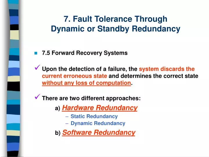
7 . Fault Tolerance Through Dynamic or Standby Redundancy. 7.5 Forward Recovery Systems Upon the detection of a failure, the system discards the current erroneous state and determines the correct state without any loss of computation . There are two different approaches:

E N D
7. Fault Tolerance Through Dynamic or Standby Redundancy • 7.5 Forward Recovery Systems • Upon the detection of a failure, the system discards the current erroneousstate and determines the correct state without any loss of computation. • There are two different approaches: a) Hardware Redundancy • Static Redundancy • Dynamic Redundancy b)Software Redundancy
7. Fault Tolerance Through Dynamic or Standby Redundancy • 7.5 Forward Recovery Systems • 7.5.1 Static Redundancy Approaches There are 3 different approaches to mask the failures: • Active Masking Redundancy • Active Masking Using Fail-Stop Modules • Active Redundancy Using Self-Diagnosis
7. Fault Tolerance Through Dynamic or Standby Redundancy • 7.5 Forward Recovery Systems • 7.5.1 Static Redundancy Approaches Active Masking Redundancy: Uses adequate level of replication to tolerate the failures, using voting on the outputs of all the replicas. • E.g.: TMR (Triple Modular Redundant) systems mask a single failure without any performance loss.
7. Fault Tolerance Through Dynamic or Standby Redundancy • 7.5 Forward Recovery Systems • 7.5.1 Static Redundancy Approaches Active Redundancy Using Fail-Stop Modules: Multiple modules of each processor actively execute each process. Each processor itself is assumed to be fail-stop. Thus, if one of the processors fails, it stops executing and the other processors executing the task continue functioning without any performance penalty, even in the presence of failures.
7. Fault Tolerance Through Dynamic or Standby Redundancy • 7.5 Forward Recovery Systems • 7.5.1 Static Redundancy Approaches • E.g.in a given system, each subsystem is duplicated, forming a pair. One of the replicas is identified as the spare. Each subsystem and its spare are, themselves, made self-checking by replication. The HW is thereby replicated 4 times. All 4 copies of the HW are tightly synchronized. When a fault is detected in a subsystem by its self-checking mechanisms, it disconnects itself as well as that the spare starts providing its service without any interruption or rollback.
7. Fault Tolerance Through Dynamic or Standby Redundancy • 7.5 Forward Recovery Systems • 7.5.1 Static Redundancy Approaches Active Redundancy Using Self-Diagnosis: Analogous to the one using “fail-stop modules”, however, instead of concurrent self-checking mechanism, self-diagnosis tasks are used to identify the faulty processor.
7. Fault Tolerance Through Dynamic or Standby Redundancy • 7.5 Forward Recovery Systems • 7.5.1 Static Redundancy Approaches • E.g.the reconfigurable duplication mechanism, where the process is replicated on 2 processors. Their outputs are continuously compared. If any mismatch indicating a failure of at least one of the processors in the pair is detected, each processor runs self-diagnostic tasks to determine if it has failed. Once the faulty processor is identified, the output of the fault-free processor can be accepted as correct. • The use of self-diagnostic tasks instead of concurrent self-checking results in a slightcomputation overhead for determining the faulty processor after a fault is detected.
7. Fault Tolerance Through Dynamic or Standby Redundancy • 7.5 Forward Recovery Systems • 7.5.2 Dynamic Redundancy Approaches Forward recovery schemes based on dynamic redundancy and checkpointing try to avoid rollback even in the presence of failures.The fault is thus tolerated without the performance penalty of a rollback. E.g.Consider a duplex system that detects failures by checkpointing the two modules in the system periodically and then, comparing their states. When a failure is detected, the roll-forward checkpointing scheme tries to determine which of the two processing modules, if any, is fault-free.
7. Fault Tolerance Through Dynamic or Standby Redundancy • 7.5 Forward Recovery Systems • 7.5.2 Dynamic Redundancy Approaches Concurrent retry in the Roll Forward Checkpointing Scheme (RFCS) Scheme.
7. Fault Tolerance Through Dynamic or Standby Redundancy • 7.5 Forward Recovery Systems • 7.5.2 Dynamic Redundancy Approaches Concurrent retry in the Roll Forward Checkpointing Scheme (RFCS) Scheme.
7. Fault Tolerance Through Dynamic or Standby Redundancy • 7.5 Forward Recovery Systems • 7.5.2 Dynamic Redundancy Approaches Variations of the RFCS may assume that each module has built-in fault detection capability such asparity checks, exception detection. Thus, 4 different scenarios can be conceptualized: Three Different Recovery Schemes (*no built-in fault detection capability included).
7. Fault Tolerance Through Dynamic or Standby Redundancy • 7.5 Forward Recovery Systems • 7.5.2 Dynamic Redundancy Approaches In an optimistic recovery strategy, one trusts the built-in detection capability to the fullest extent. This scheme will not require the use of a spare, even though it may be available. Module I1 I2 A Optimistic schemewith orwithout spare.Roll-forward (I) I1 I2 B roll-forward
7. Fault Tolerance Through Dynamic or Standby Redundancy • 7.5 Forward Recovery Systems • 7.5.2 Dynamic Redundancy Approaches Pessimistic Scheme with spare rolling forward with all single faults. In the pessimistic recovery strategy, It may be noted that although module B has been already suspect to be faulty, a more conservative action was taken just in case A might have experienced a failure which escaped the built-in detection capability during I1. Pessimistic schemes. Pessimistic Scheme with spare rolling back with double faults.
7. Fault Tolerance Through Dynamic or Standby Redundancy • 7.5 Forward Recovery Systems • 7.5.2 Dynamic Redundancy Approaches The ideal curve 1 is preferred because it allows a small reduction in reliability to be traded off against a large gain in performance. (This is the case of Optimistic Recovery Strategies). Reliability 1 2 3 Three different roll-forward schemes. Performance
7. Fault Tolerance Through Dynamic or Standby Redundancy • 7.5 Forward Recovery Systems • 7.5.2 Dynamic Redundancy Approaches • Generally, the mean completion time given a failure has occurred is lower for the roll-forward scheme for both optimistic and pessimistic strategies. • Without any failure, all the schemes perform similarly. • When there is no built-in detection capability, the pessimistic and the corresponding optimistic schemehave identical reliabilities. Since there is no built-in detection, there is no way to identify the faulty module without comparison between operatingmodulesandthespareone. • When there is 100% fault detection, with or without spare schemes have identical reliabilities.
7. Fault Tolerance Through Dynamic or Standby Redundancy • 7.5 Forward Recovery Systems • 7.5.2 Dynamic Redundancy Approaches Note: = failure rate; c= detection coverage (indicates the degree of built- in detection capabilities); n = # of checkpoint intervals.
7. Fault Tolerance Through Dynamic or Standby Redundancy • 7.5 Forward Recovery Systems • 7.5.2 Dynamic Redundancy Approaches Roll-forward Rollback Optimistic Pessimistic Performance comparison between optimistic and pessimistic schemes: mean completion time, given a fault. (Optimistic scheme is better) Reliability comparison between optimistic and pessimistic schemes. (Pessimistic scheme is better)
7. Fault Tolerance Through Dynamic or Standby Redundancy • 7.5 Forward Recovery Systems • 7.5.2 Dynamic Redundancy Approaches One of the important advantages of a roll-forward scheme is in the minimal degradation in I/O performance: All outputs after I1 will experience one checkpoint interval delay. Permanent delay in rollback scheme outputs in the event of a fault.
7. Fault Tolerance Through Dynamic or Standby Redundancy • 7.5 Forward Recovery Systems • 7.5.2 Dynamic Redundancy Approaches The outputs x and y are the only ones delayed and all other outputs are will occur at the regularly scheduled interval. Module x,y,z w v : System outputs A I1 I2 I3 I4 I5 I6 B I1 I2 I3 I4 I5 I6 I1 I2 Spare Activated Spare Release Temporary delay in roll-forward scheme outputs in the event of a fault.
7. Fault Tolerance Through Dynamic or Standby Redundancy • 7.5 Forward Recovery Systems • 7.5.2 Dynamic Redundancy Approaches Forward Recovery Using Checkpointing.
7. Fault Tolerance Through Dynamic or Standby Redundancy • 7.5 Forward Recovery Systems • 7.5.3 Software Redundancy-Based Approach for Forward Error Recovery The previous approaches primarily require HW redundancy (+300%). This approach requires a certain degree ofSW redundancy, as well as HW redundancy: SW redundancy is implemented byusing Recovery Blocks. Recovery blocks are a language construct that supports the incorporation of program redundancy into a fault-tolerant program in a concise and easily readable form.
7. Fault Tolerance Through Dynamic or Standby Redundancy • 7.5 Forward Recovery Systems • 7.5.3 Software Redundancy-Based Approach for Forward Error Recovery The syntax of the recovery block is: Ensure T by B1 else by B2 . . . else by Bn else error Where: T is acceptance test; B1 denotes the primary try block; Bk denotes the (k – 1)th alternate try block.
7. Fault Tolerance Through Dynamic or Standby Redundancy • 7.5 Forward Recovery Systems • 7.5.3 Software Redundancy-Based Approach for Forward Error Recovery Distributed Recovery Block.