Download
1 / 53
590 likes | 912 Views
DVB Digital Video Broadcasting. DVB systems distribute data using a variety approaches, including by satellite (DVB-S, DVB-S2), cable (DVB-C), terrestrial television (DVB-T) and terrestrial television for handhelds (DVB-H).

E N D
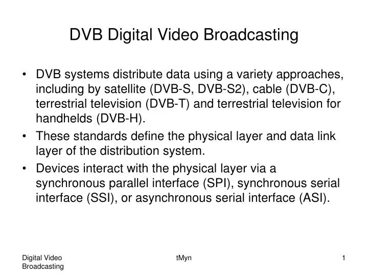
DVB Digital Video Broadcasting • DVB systems distribute data using a variety approaches, including by satellite (DVB-S, DVB-S2), cable (DVB-C), terrestrial television (DVB-T) and terrestrial television for handhelds (DVB-H). • These standards define the physical layer and data link layer of the distribution system. • Devices interact with the physical layer via a synchronous parallel interface (SPI), synchronous serial interface (SSI), or asynchronous serial interface (ASI). tMyn
DVB-T stands for Digital Video Broadcasting – Terrestrial and it is the DVB European consortium standard for the broadcast transmission of digital terrestrial television. • This system transmits a compressed digital audio/video stream, using OFDM modulation with concatenated channel coding (i.e. COFDM). • The adopted source coding methods are MPEG-2 and, more recently, H.264. • Figure 1 gives a functional block diagram of the system. tMyn
Source coding and MPEG-2 multiplexing Splitter MUX adaptation, energy dispersal External interleaver Internal encoder Internal interleaver External encoder MUX adaptation, energy dispersal External interleaver Internal encoder External encoder DAC and Front End Guard interval insertion Frame adaptation OFDM Mapper AERIAL TPS and pilot signal Figure 1. Functional block diagram of the DVB-T system. tMyn
Source encoding and MPEG-2 multiplexing. • Compressed video, audio and data streams are multiplexed into Programme Streams (PS). • One or more PSs are joined together into an MPEG-2 Transport Stream (MPEG-2 TS), this is the basic digital stream which is being transmitted and received by home Set Top Boxes (STB). • Allowed bitrates for the transported data depend on number of coding and modulation parameters, it can range from about 5 Mbits/sec to about 32 Mbits/sec. tMyn
Splitter • Two different TSs can be transmitted at the same time, using a technique called Hierarchical Transmission. • It may be used to transmit, for example, a standard definition SDTV signal and a high definition HDTV signal on the same carrier. • Generally, the SDTV signal is protected better than the HDTV one. • At the receiver, depending on the quality of the received signal, the STB may be able to decode the HDTV stream, or, if signal strength lacks, it can switch to the SDTV one. tMyn
In this way, all receivers that are in the proximity of the transmission site can lock the HDTV signal, whereas all the other ones, even the farthest, may still be able to receive and decode a SDTV signal. tMyn
MUX adaptation and energy dispersal • The MPEG-2 TS is identified as a sequence of data packets, of fixed length (188 bytes). • With a technique called energy dispersal, the byte sequence is decorrelated. • This randomization ensures adequate binary transitions. • The process is accomplished with the Pseudo Random Binary Sequence (PRBS) generator. tMyn
External encoder • A first level of protection is applied to the transmitted data, using a nonbinary block code, a Reed-Solomon RS(204, 188) code, allowing the correlation of up to maximum of 8 wrong bytes for each 188-byte packet. tMyn
External interleaver • Convolutional interleaving is used to rearrange the transmitted data sequence, such way it becomes more rugged to long sequences of errors, Figure 2. tMyn
MPEG-2 transport MUX packet 8 Transport MUX packets PRBS period=1503 bytes … … Randomized transport packets: SYNC bytes and Randomized Data bytes Figure 2a. Steps in the process of adaptation, energy dispersal, outer coding and interleaving. tMyn
204 bytes Reed-Solomon RS(204, 188, 8) error protected packets Data structure after outer interleaving; interleaving depth I=12 bytes : Non randomized complemented sync byte SYNCn: Non randomized sync byte, n=2, 3, …, 8 Figure 2b. Steps in the process of adaptation, energy dispersal, outer coding and interleaving. tMyn
Internal encoder • A second level of protection is given by a punctured convolutional code, which is often denoted in STBs menus as FEC (Forward Error Correction). • There are five valid coding rates: 1/2 (unpunctured), 2/3, 3/4, 5/6, and 7/8. • Puncturing is a technique used to make a m/n rate code from a basic rate 1/2 code. • It is reached by deletion of some bits in the encoder output. • Bits are deleted according to puncturing matrix, Figure 3. tMyn
For example, if we want to make a code with rate 2/3 using the appropriate matrix from the table, we should take a basic encoder output and transmit every second bit from the first branch and every bit from the second one. • The specific order of transmission is defined by the respective standard. tMyn
Internal interleaver • Data sequence is rearranged again, aiming to reduce the influence of burst errors. • This time, a block interleaving technique is adopted, with a pseudo-random assignment scheme (this is really done by two separate interleaving processes, one operating on bits and another one operating on groups of bits). • The input (up to two bit streams) to the internal interleaver is demultiplexed into n sub-streams, where n=2 for QPSK, n=4 for 16-QAM, and n=6 for 64-QAM. • In non-hierarchical mode, the single input stream is demultiplexed into n sub-streams. tMyn
Each sub-stream from the demultiplexer is processed by a separate bit interleaver. • There are therefore up to six interleavers depending on n, labelled I0 to I5. • I0 and I1 are used for QPSK, I0 to I3 for 16-QAM and I0 to I5 for 64-QAM. • Bit interleaving is performed only on the useful data. • The block size is the same for each interleaver, but the interleaving sequence is different in each case. • The bit interleaving block size is 126 bits. tMyn
The block interleaving process is therefore repeated exactly twelve times per OFDM symbol of useful data in the 2K mode (12*126=1512 bits) and forty-eight times per symbol in the 8K mode (48*126=6048 bits). • The outputs of the n interleavers are grouped to form the digital data symbols, such that each symbol of n bits will consist of exactly one bit from each of the n interleavers. • Hence, the output from the bit-wise interleaver is a n bit word. tMyn
The purpose of the symbol interleaver is to map n bit words onto the 1512 (2K mode) or 6048 (8K mode) active carriers per OFDM symbol. • The symbol interleaver acts on blocks of 1512 (2K mode) or 6048 (8K mode) data symbols. tMyn
Mapper • The digital bit sequence is mapped into a base band modulated sequence of complex symbols. • The system uses Orthogonal Frequency Division Multiplex (OFDM) transmission. • All data carriers in one OFDM frame are modulated using either QPSK, 16-QAM, 64-QAM, non-uniform 16-QAM or non-uniform 64-QAM constellations. • The exact proportions of the constellations depend on a parameter α, which can take the three values 1, 2 or 4. tMyn
α is the minimum distance separating two constellation points carrying different HP-bit values divided by the minimum distance separating any two constellation points, Figure 4. • Non-hierarchical transmission uses the same uniform constellation as the case with α=1. • The exact values of the constellation points are z∈{n+jm} with values of n, m given below for the various constellations: QPSK n∈{-1, 1}, m∈{-1, 1} tMyn
d 4d Figure 4. Non-uniform, hierarchical 64-QAM with α=4. tMyn
16-QAM (non-hierarchical and hierarchical with α=1) n∈{-3, -1, 1, 3}, m∈{-3, -1, 1, 3} Non-uniform 16-QAM with α=2 n∈{-4, -2, 2, 4}, m∈{-4, -2, 2, 4} Non-uniform 16-QAM with α=4 n∈{-6, -4, 4, 6}, m∈{-6, -4, 4, 6} tMyn
64-QAM (non-hierarchical and hierarchical with α=1) n∈{-7, -5, -3, -1, 1, 3, 5, 7}, m∈{-7, -5, -3, -1, 1, 3, 5, 7} Non-uniform 64-QAM with α=2 n∈{-8, -6, -4, -2, 2, 4, 6, 8}, m∈{-8, -6, -4, -2, 2, 4, 6, 8} Non-uniform 64-QAM with α=4 n∈{-10, -8, -6, -4, 4, 6, 8, 10}, m∈{-10, -8, -6, -4, 4, 6, 8, 10} • Some examples are in Figure 5. tMyn
10 00 1 1 -1 -1 10 01 Figure 5a. The QPSK mapping and the corresponding bit patterns, Non-hierarchical, and hierarchical with α=1. tMyn
1000 0010 1010 0000 3 1001 1011 0011 0001 1 -3 3 -1 1 0111 1101 1111 0101 -1 1100 1110 0110 0100 -3 Figure 5b. The 16-QAM mapping and the corresponding bit patterns, Non-hierarchical, and hierarchical with α=1. tMyn
001010 100010 101010 000010 001000 100000 101000 000000 7 101011 001011 001001 000011 100001 100011 101001 000001 5 100101 001101 001111 000111 000101 100111 101111 101101 3 100110 101100 001110 000100 100100 101110 000110 001100 1 011100 111110 010100 111100 110110 011110 010110 110100 -1 111111 011101 110101 011111 010111 110111 111101 010101 -3 111001 110001 011001 011011 010011 110011 111011 010001 -5 110010 111010 011000 011010 010010 110000 111000 010000 -7 Figure 5c. The 64-QAM mapping and the corresponding bit patterns, Non-hierarchical, and hierarchical with α=1. tMyn
Frame adaptation • The transmitted signal is organized in frames. • Each frame has a duration of TF and consists of 68 OFDM symbols. • Four frames constitute one super-frame. • Each symbol is constituted by a set of K=6817 carriers in the 8K mode and K=1705 carriers in the 2K mode and transmitted with a duration TS. • It is composed of two parts: a useful part with duration TU and a guard interval with a duration Δ. • The guard interval consists in a cyclic continuation of the useful part TU and is inserted before it. tMyn
Four values of guard intervals may be used, Figure 6. • The symbols in an OFDM frame are numbered from 0 to 67. • All symbols contain data and reference information. • Since the OFDM signal comprises many separately-modulated carriers, each symbol can in turn be considered to be divided into cells, each corresponding to the modulation carried on one carrier during one symbol. tMyn
Figure 6. Duration of symbol part for the allowed guard intervals for 8 MHz channels. tMyn
Pilot and TPS signals • In order to simplify the reception of the signal being transmitted on the terrestrial radio channel, additional signals are inserted in each block. • Pilot signals (scattered pilot cells, continual pilot carriers) can be used for frame synchronization, frequency synchronization, time synchronization, channel estimation, transmission mode identification and also to follow the phase noise. • Transmission Parameters Signalling (TPS) signals are used to send the parameters of the transmitted signal and to unequivocally identify the transmission cell. tMyn
It should be noted that the receiver must be able to synchronize, equalize and decode the signal to gain access to the information held by the TPS pilots. • Thus, the receiver must know this information beforehand, and the TPS data is only used in special cases, such as changes in the parameters, resynchronizations, etc. tMyn
OFDM Modulation • The sequence of blocks is modulated according to the OFDM technique, using 2048, 4096, or 8192 carriers (2K, 4K, 8K mode, respectively). • Orthogonal Frequency-Division Multiplexing – essentially identical to Coded OFDM – is a digital multi-carrier modulation scheme, which uses a large number of closely-spaced orthogonal sub-carriers. • Each sub-carrier is modulated with a conventional modulation scheme (such as quadrature amplitude modulation) at a low symbol rate, maintaining data rates similar to conventional single-carrier modulation schemes in the same bandwidth. tMyn
In practice, OFDM signals are generated using the Fast Fourier transform algorithm. • The primary advantage of OFDM over single-carrier schemes is its ability to cope with severe channel conditions – for example, multipath and narrowband interference – without complex equalization filters. • Channel equalization is simplified because OFDM may be viewed as using many slowly-modulated narrowband signals rather than one rapidly-modulated wideband signal. • The orthogonality of the sub-carriers results in zero cross-talk, even though they are so close that their spectra overlap. tMyn
Low symbol rate helps manage time-domain spreading of the signal (such as multipath propagation) by allowing the use of a guard interval between symbols. • The guard interval also eliminates the need for a pulse-shaping filter. • The carriers are indexed by k∈[Kmin; Kmax] and determined by Kmin=0 and Kmax=1704 in 2K mode and Kmax=6816 in 8K mode respectively. • The spacing between adjacent carriers is 1/TU while the spacing between carriers Kmin and Kmax are determined by (K-1)/TU. • The numerical values for the OFDM parameters are given in Figure 7. tMyn
Figure 7. Numerical values for the OFDM parameters for the 8K and 2K modes for 8 MHz channels. tMyn
The values for the various time-related parameters are given in multiples of the elementary period T and in microseconds. • The elementary period T is 7/64 μs for 8 MHz channels. tMyn
Guard interval insertion • To decrease receiver complexity, every OFDM block is extended, copying in front of it its own end (cyclic prefix). • The width of such guard interval can be 1/32, 1/16, 1/8, or 1/4 that of the original block length, Figure 6. tMyn
DAC and front-end • The digital signal is transformed into an analog signal, with a digital-to-analog converter (DAC), and then modulated to radio frequency (UHF) by the RF front-end. • The occupied bandwidth is designed to accommodate each single DVB-T signal into 8 MHz wide channels. • Available bitrates for DVB-T system in 8 MHz channels are presented in Figure 8. All decimal values are in Mbit/s. tMyn
Figure 8. Available bitrates for a DVB-T system in 8 MHz channels. tMyn
DVB-C stands for Digital Video Broadcasting – Cable and it is the DVB European consortium standard for the broadcast transmission of digital television over cable. • This system transmits an MPEG-2 family digital audio/video stream, using a QAM modulation with channel coding. • Figure 9 gives a functional block diagram of the system. tMyn
Source coding and MPEG-2 multiplexing MUX adaptation, energy dispersal Byte/m-tuple conversion Differential encoding Channel encoder Interleaver DAC and Front End Base-band shaping QAM mapper RF Cable Channel Figure 9. Functional block diagram of the DVB-C system. tMyn
Source coding and MPEG-2 multiplexing • Basically the same as with DVB-T MUX adaptation and energy dispersal • Basically the same as with DVB-T Channel encoder • Basically the same as with DVB-T External encoder Interleaver • Basically same as with DVB-T External interleaver tMyn
Byte/m-tuple conversion • This unit shall perform a conversion of the bytes generated by the interleaver into QAM symbols. • Depending on if there is 16-QAM, 32-QAM … , or 256-QAM, m=4, 5, 6, 7, or 8. Differential encoding • In order to get a rotation-invariant constellation, this unit shall apply a differential encoding of the two most significant bits of each symbol. tMyn
QAM Mapper • The bit sequence is mapped into a base-band digital sequence of complex symbols. • The modulation of the system is quadrature amplitude modulation with 16, 32, 64, 128, or 256 points in the constellation diagram. • Notice! The mapping is not identical with the correspondent mapping of DVB-T. tMyn
Base-band shaping • The QAM signal is filtered with a raised-cosine shaped filter, in order to remove mutual signal interference at the receiving side. DAC and front-end • The digital signal is transformed into an analog signal, with a digital-to-analog converter, and then modulated to radio frequency by the RF front-end. tMyn
The standard paper says: “With a roll-off factor of 0.15, the theoretical maximum symbol rate in an 8 MHz channel is about 6.96 MBaud”. • This piece of information gives rise to the following figure, Figure 10. All decimal numbers are in Mbit/s. tMyn
Figure 10. Available bitrates for DVB-C system in an 8 MHz channel. tMyn
The latest DVB-C specification is DVB-C2. • Modes and features of DVB-C2 in comparison to DVB-C: tMyn
DVB-C DVB-C2 The final DVB-C2 specification was approved by the DVB Steering Board in April 2009. [2] Modes and features of DVB-C2 in comparison to DVB-C: [2] tMyn
Main features of the DVB-S2: • Source may be one or more MPEG-2 TS (MPEG-2 Transport Stream). Packet streams other than MPEG-2 are also valid (MPEG-4 AVC/H.264). • MPEG-2 TS are supported using a compatibility mode, whereas the native stream format for DVB-S2 is called Generic Stream (GS). • Adaptative mode: this block is heavily dependent on the application that generates the data. This means: tMyn