Download
1 / 13
130 likes | 262 Views
Lecture 16: Router Design. Topics: router pipelines, case studies – Alpha, Intel. Router Functions. Crossbar, buffer, arbiter, VC state and allocation, buffer management, ALUs, control logic Typical on-chip network power breakdown: 30% link 30% buffers 30% crossbar.

E N D
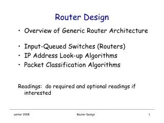
Lecture 16: Router Design • Topics: router pipelines, case studies – Alpha, Intel
Router Functions • Crossbar, buffer, arbiter, VC state and allocation, • buffer management, ALUs, control logic • Typical on-chip network power breakdown: • 30% link • 30% buffers • 30% crossbar
Virtual Channel Router • Buffers and channels are allocated per flit • Each physical channel is associated with multiple virtual • channels – the virtual channels are allocated per packet • and the flits of various VCs can be interweaved on the • physical channel • For a head flit to proceed, the router has to first allocate • a virtual channel on the next router • For any flit to proceed (including the head), the router has • to allocate the following resources: buffer space in the • next router (credits indicate the available space), access • to the physical channel
Router Pipeline • Four typical stages: • RC routing computation: the head flit indicates the VC that it belongs to, the VC state is updated, the headers are examined and the next output channel is computed (note: this is done for all the head flits arriving on various input channels) • VA virtual-channel allocation: the head flits compete for the available virtual channels on their computed output channels • SA switch allocation: a flit competes for access to its output physical channel • ST switch traversal: the flit is transmitted on the output channel A head flit goes through all four stages, the other flits do nothing in the first two stages (this is an in-order pipeline and flits can not jump ahead), a tail flit also de-allocates the VC
Router Pipeline • Four typical stages: • RC routing computation: compute the output channel • VA virtual-channel allocation: allocate VC for the head flit • SA switch allocation: compete for output physical channel • ST switch traversal: transfer data on output physical channel STALL Cycle 1 2 3 4 5 6 7 Head flit Body flit 1 Body flit 2 Tail flit RC VA SA ST RC VA SA SA ST -- -- SA ST -- -- -- SA ST -- -- SA ST -- -- -- SA ST -- -- SA ST -- -- -- SA ST
Stalls • Causes behind stalls: • RC fail: new head flit arrives, but the previous packet’s tail flit is still competing for its output port • VA fail because no VCs available • SA fail because no credits (buffers) available • SA fail because no channel available
Speculative Pipelines • Perform VA, SA, and ST in • parallel (can cause collisions • and re-tries) • Typically, VA is the critical • path – can possibly perform • SA and ST sequentially • Perform VA and SA in parallel • Note that SA only requires knowledge • of the output physical channel, not the VC • If VA fails, the successfully allocated • channel goes un-utilized Cycle 1 2 3 4 5 6 7 Head flit Body flit 1 Body flit 2 Tail flit RC VA SA ST RC VA SA ST -- SA ST SA ST -- SA ST SA ST -- SA ST SA ST • Router pipeline latency is a greater bottleneck when there is little contention • When there is little contention, speculation will likely work well! • Single stage pipeline?
Case Study I: Alpha 21364 Router • Integrates a router on-chip to create a multiprocessor • building block (up to 128 processors in a 2D torus) • 4 external ports, deep 8-stage pipeline for high frequency, • speculation, adaptive routing, cut-through flow control • (resources per packet, the largest packet in the coherence • protocol is only 76 B (19 flits), 316 packet buffers per router) • Physical channels are allocated per packet – VCs enable • deadlock avoidance • Per-hop latency of 10.8 ns (13 processor cycles)
Alpha 21364 Pipeline Switch allocation – local Update of input unit state Switch allocation – global Routing Append ECC information RC T DW SA1 WrQ RE SA2 ST1 ST2 ECC Transport/ Wire delay Switch traversal Write to input queues
Recent Intel Router • Used for a 6x6 mesh • 16 B, > 3 GHz • Wormhole with VC • flow control Source: Partha Kundu, “On-Die Interconnects for Next-Generation CMPs”, talk at On-Chip Interconnection Networks Workshop, Dec 2006
Recent Intel Router Source: Partha Kundu, “On-Die Interconnects for Next-Generation CMPs”, talk at On-Chip Interconnection Networks Workshop, Dec 2006
Recent Intel Router Source: Partha Kundu, “On-Die Interconnects for Next-Generation CMPs”, talk at On-Chip Interconnection Networks Workshop, Dec 2006
Title • Bullet