Download
1 / 50
710 likes | 2.03k Views
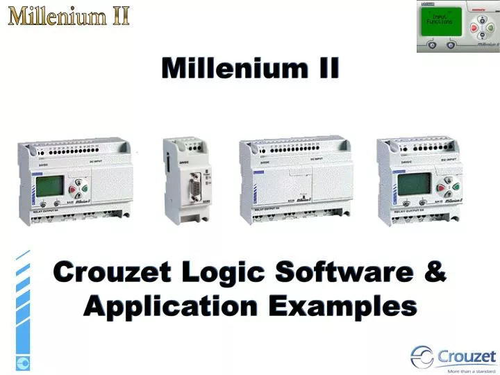
Millenium II Crouzet Logic Software & Application Examples. The different controllers. The Functions. Input functions Function blocks Dedicated function blocks Logic functions Output functions Applications Examples. Digital input. Illuminated pushbutton. Contact.

E N D
Millenium II Crouzet Logic Software & Application Examples
The Functions • Input functions • Function blocks • Dedicated function blocks • Logic functions • Output functions • Applications Examples
Digital input Illuminated pushbutton Contact Selector switch Limit switch Pushbutton Proximity sensor Normally open relay Presence detector
Analogue Input: This type of input can take an input voltage of 0 to 10 V corresponding to a value of 0 to 255. Numeric & Analogue filtered Inputs: These types of input can be used to suppress interference. Numeric Input: With an XT20 it is possible to communicate a counter value to the extension. Constant Inputs: Both analogue and digital constants.
This is an internal clock with a period of one second. Buttons: you can use the buttons on the front panel of the Millenium: A, B, ESC, OK, + and - in your application. Daylight saving: For “summer time”
The Boolean function takes four inputs. The output reacts according to the truth table described in the parameters.
Rocker switch: generating a pulse on S or R will Set or Reset the output. The priority defines the output state when both inputs are at 1.
Time delay: This is used to apply an ON delay, an OFF delay, or both delays to the output signal in relation to the input signal. Input Function A Function C Function AC
Preset counter:This function is used to count up to a defined value. Once this value has been reached, the output changes to 1 until reset if the fixed output is selected, or for a certain period if the pulse output is selected.
Max Limit Min Limit Zone comparison: Used for applications using analogue data. Input Run in the zone Output Stop in the zone
BW timer: This generates a cycle duration pulse on a rising or falling edge or on both edges of an input, according to the setting chosen in the parameters. input ouput
Hour meter This function measures the duration of the input state at 1. After a preset duration, the output changes state. This block can, for example, be used as an alert on a machine for maintenance purposes.
Pulse: This is used to generate pulses on a rising edge of the input.
Monostable: This block is used to generate 1 pulse on a rising edge of the input.
Schmitt trigger: The output changes state if the input is lower than the minimum value, and the output changes state again if the input is higher than the maximum value. If the input is between the two, the output remains unchanged. This function is used to locate a high threshold and low threshold in relation to an analogue variable..
Comparison of 2 values: This block is used to compare two analogue values using the =, >, <,,, operators. The digital output is activated if the comparison is true.
Gain: Function which allows the use of a scale factor and is applicable to all analogue data.
Display on the LCD: This block is used to display text or an integer on the front panel LCD display. For example, you can display a decimal derived from an integer.
24-hour, 7-day and 365-day timer switch: This function is used to activate or deactivate the output at a precise moment in the day, week or year.
Multiplexing: This function multiplexes the integers. It is used to route on the output either the value of the CHANNEL A input when the CONTROL input is set to OFF or the value of the CHANNEL B input when the CONTROL input is set to ON. Bistable: The principle of this block is very well known, since it involves an impulse relay. Essentially a flip-flop, the initial impulse will set the output to 1, and the ensuing pulse will reset the output to 0.
Cam timer: If the FORWARD input changes from OFF to ON, a group of 8 integral cam wheels will move forward one step. The function presents ON or OFF values (parameter inputs) for the number of the step indicated on the POSITION output (0 to 49) on the 8 outputs (OUTPUT 1 to OUTPUT 8).
Pumps management: This function is used to set to ON a maximum of four digital outputs which can be activated (OUTPUT 1 ... OUTPUT 4). In addition, the outputs set to ON are selected so that in the event of prolonged operation, each output will have been set to ON the same number of times.
Up / Down counter: Counts values up and down, setting the output ON when the preset value is reached. The output goes back OFF if the value on the down-count input causes the counter value to fall under the preset value. Archive: This function is used to record and keep track of a special event ( alarm, counter value, time, over heating…). Multiplication division Addition subtraction: Used to multiply simple values but also counter values Modif time prog: It is a user friendly, front panel configuration for time switch display.
Graphcet Functions: SFC functions are similar to Grafcet language. The principle is simple, since it involves sequential programming, with steps succeeding one another surrounded by transitions. When a step is active, wait for the next transition to become active in order to go to the next step.
Initial Step and Resettable initial step: This function can be used to set up an operating phase or step for a PLC or a device. This reinitialisation, which has priority over all the input values of an independent SFC chart, forces a status token to its own state and all other functions to their initial states • The non-connected TRANSITION is maintained in the OFF state: transition blocked • The non-connected STEP INPUT 1 or STEP INPUT 2 is maintained with no token present in the step input. • The non-connected REINITIALISATION is maintained in the OFF state: The associated function cannot reinitialise the independent SFC chart with which it is associated.
A OR convergence is used to link an identical operating phase after one or other operating phases (simultaneous or not). Operating in progress: Step1 of B01 active. (stable state) End of operating phase 1: transition B01 active (transient state) Operating phase 3 in progress: Step B03 active (stable state) Active step Status token circulation Active step
The AND convergence function is used to link a single operating phase after simultaneous operating phases. Operating phase 1 & 2 in progress: Step 1 & 2 of B01 are active simultaneously (stable state) End of operating phase 1& 2: Transition B01 active (transient state)(transient state) Operating phase 3 in progress: Step B02 (stable state) (stable state) Active step Active step Active step
OR Divergence is used to link one or two operating phases after an operating phase. Operating phase 1 in progress: Step B01 active (stable state) End of operating phase 1. Transition 2 of B01 active (transient state) Operating phase 3 in progress: Step B00 active (stable state) Active Step Active step
AND Divergence to is used to represent and control simultaneous operating phases. Operating phase 1 in progress: Step B01 active (stable state) End of operating phase 1. Transition B01 active (transient state) Operating phase 2& 3 in progress simultaneously: Step B00 & B04active (stable state) Active step Active step Active step
This function logically ANDs the connected digital input signals. If at least one INPUT is set to OFF, the OUTPUT is set to OFF. If all the connected INPUTS are set to ON, the OUTPUT is set to ON. This function logically ORs the connected digital input signals. If at least one INPUT is set to ON, the OUTPUT is set to ON. If all the connected INPUTS are set to OFF, the OUTPUT is set to OFF. This function logically NEGATIVELY ANDs the connected digital input signals. If at least one INPUT is set to OFF, the OUTPUT is set to ON. If all the connected INPUTS are set to ON, the OUTPUT is set to OFF. This function logically NEGATIVELY ORs the connected digital input signals. If at least one INPUT is set to ON, the OUTPUT is set to OFF. If all the connected INPUTS are set to OFF, the OUTPUT is set to ON.
This function exclusively logically ORs the connected digital input signals. If both INPUTS are at the same level (both set to ON or both set to OFF), the OUTPUT is set to OFF. If one of the inputs is set to ON and the other is set to OFF, the output is set to ON. This function logically NOTs the connected digital input signals. If the INPUT signal is set to OFF, the OUTPUT is set to ON. If the INPUT signal is set to ON, the OUTPUT is set to OFF.
Digital Outputs Normally open relay Audible signal Fan Indicator Lamp Green light Solid State Relay Red light Valve Orange light Cylinder Heater Motor Resistor
Pulse Width Modification Output The input (internal controller input) of the PWM output is an integer value. The value of an integer at the output of an FBD function block can be between -32767 and +32767. The PWM only takes into account values between 0 and 255: this means that all input values less than 0 are reset to 0 and that all values greater than 255 are reset to 255. This value between 0 and 255 is used in the PWM to vary the cyclic ratio of a digital clock. For example: with the value 0, the output signal is always at 0 with the value 127, the output signal is at 0 for half the time and at 1 for half the time: the filtered analog output is produced at half the supply voltage of the output unit finally, with the value 255, the output signal is always at 1 and the analog output takes the maximum value of the supply voltage of the unit. [-32767; 0] 127 200 [255; 32767] Input 1 1 1 Output 0 50% 79% 100%
Num Out This function is used to output a 16-bit integer (-32768, +32767) from certain connected extensions. This input can only be placed on INTEGER type output units of the extensions. Back Light This output symbol cannot be placed on the output units of the controller. Backlighting of the LCD screen on the front panel of the controller. The screen is not lit when the input is in the OFF state. In simulation and monitoring modes, when the input is set to ON, the following symbol appears. Input ON: the LCD screen is back-lit
Timer A-C Three timing Functions in one block. Delay on Make Function A Upon receiving an input signal timing begins. After the set time has elapsed the output is activated. The output remains active until removal of the input signal. Combination Delay on Make / Delay on Break Function AC Upon receiving the input signal the delay on make time begins. After the set time has elapsed the output is activated. Upon removal of the input signal, the delay on break time begins. After the set time has elapsed the output is de-activated. Delay on and delay off times are independently adjustable. Delay on Break Function C Upon receiving the input signal the output is activated. Timing begins with removal of the input signal. After the set time has elapsed the output is de-activated
Timer BH Single Shot Function B Upon receiving an input signal the output is activated and timing begins. After the set time has elapsed the output is de-activated. The input signal has no effect on the timer until the output is de-activated Interval Function H Upon receiving an input signal the output is activated and timing begins. After the set time has elapsed the output is de-activated.If the input signal is removed before time-out, timing will reset and the output is de-activated.
Repeat Cycle Timer, Counter, Set Reset In this example, a momentary push button is pressed to start the cycle. The Timer Li function Block is set to flash the light bulb on for 1second and off for 1 second. The Timer Li function block can also be programmed to repeat this cycle a set number of times. In this example the timer has been programmed to repeat the cycle 10 times. The Set Reset Function Block is used to latch the momentary push button. The Preset Counter is used to count the number of flashes and reset the Set Reset.
Temperature Sensing In this example, a Crouzet 89750150 temperature sensor is wired to a Millenium analog input. The Gain Function Block scales the 8 bit analog to digital converter to degrees Fahrenheit. This particular sensor measures 14 to 104 degrees. The value of the gain is fed into the compare. The Num Function Block is used to feed a set value into the Compare Function. In this example, the value of num is set to 80. The compare function block is programmed to give an output if the gain value is greater than the num block value. If the temperature goes above 80 degrees the Millenium will turn on a fan.
Boolean - Complex Logic in a single Function = In this example, both of these diagrams perform the same function. The Boolean function block is programmed via a truth table. You can set the block to activate it’s output on any combination of the 4 inputs.
Multiple Displays In this example, The ‘A’ key on the front face of the Millenium is used to page through five separate displays. At start-up the current count of the counter is 0, the first compare is set to be active when the counter is at 0. When the A button is pressed the counter increments. The value of the counter is now 1 and the second compare is programmed to be active for this counter value. The counter’s set point is programmed for the number of displays in the sequence (5 in this example). The counter is also programmed to be in repeat mode, so the counter resets at 5 and the first display is then active again.
Addition/Subtraction Function Block In this example, The Addition/Subtraction block is used to add(top example) or subtract(bottom example) two analog values. Input 6 and 7 are programmed to be analog inputs. The two gain function blocks scale the number to a meaningful value. The two gain blocks feed the add or subtract inputs on the add/subtract function block. The result of the math is displayed on the LCD and is also fed to the compare. The counter preset value is used to feed the compare a user adjustable value. The second display allows modification of the counter preset.
Rate Meter / Tachometer In this example, a proximity sensor is used to determine rpm of a rotating object. Rpm is displayed on the LCD, and compared against a fixed value. The prox is wired to a Boolean block. The Boolean block only gives an output if the prox is on and the Timer B06 is NOT on. The counter counts the pulses of the prox for one second. The value of the counter is then multiplied to determine rpm. The archive block is used to store that value and display it on the LCD. The archive block is updated once every 1.2 seconds. The Time B06 controls the operation. The timer has 1 second off time and a .2 second on time. The off time is used to count the pulses. The on time triggers the archive to latch in the rpm, and start the delay timer. The timer delays .2 seconds then resets the counter for the next sample. The compare function turns on an output when a certain rpm is reached, this value is programmed into the NUM block B11