Download
1 / 13
130 likes | 271 Views
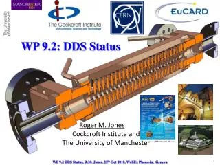
WP 9.2: DDS Status. Roger M. Jones Cockcroft Institute and The University of Manchester. 1. WP 9.2 DDS Status, R.M. Jones, 25 th Oct 2010, WebEx Phone-in, Geneva. Summary of CLIC_DDS_C . Dipole mode. Manifold mode. Manifold. ∆f=3.6 σ =2.3 GHz ∆f/fc=13.75%. Coupling slot.

E N D
WP 9.2: DDS Status Roger M. JonesCockcroft Institute andThe University of Manchester 1 WP 9.2 DDS Status, R.M. Jones, 25th Oct 2010, WebEx Phone-in, Geneva
Summary of CLIC_DDS_C Dipole mode Manifold mode Manifold ∆f=3.6 σ =2.3 GHz ∆f/fc=13.75% Coupling slot 24 cells No interleaving Meets design Criterion? ∆fmin = 8.12 MHz ∆tmax =123 ns ∆s = 36.92 m ∆fmin = 65 MHz ∆tmax =15.38 ns ∆s = 4.61 m 192 cells 8-fold interleaving 192 cells 8-fold interleaving
CLIC_DDS_E Elliptical Design –E Fields Circular Square Single undamped cell Iris radius=4.0 mm Convex ellipticity Concave ellipticity ε=-8.28 ε=-2.07 ε=-4.14
CLIC_DDS_E Elliptical Design, Single Undamped Cell Dependence of Fields on Iris radius = 4. 0 mm Iris thickness = 4.0 mm Chosen design
CLIC_DDS_A Wake 24 cells No interleaving • Wake of a non-interleaved 24 cell structure –first structure of 8-fold interleaved structure chosen. • Motivated by high gradient testing • Wake is measurable and provides a useful comparison to simulations (but will not, of course, meet beam dynamics criteria) Undamped Qavg ~1700 Damped 24 cells No interleaving
Matching CLIC_DDS_A I/P • Firstly, match-out either end of structure with regular cells: • Structure for test will utilise a mode launcher • Initially, simulate a structure with one regular cell and two matching cells at either end and we study the minima in S11 as a function of the geometrical parameters of the matching cells (a, L –adopt L variation, rather than b, from space considerations) • Add additional (2, then 3) identical standard cells (const. imp) and follow the same procedure and modify parameters of matching cells to minimise S11 • The matching condition (on a, L) is that which coincident with all 3 simulations. • Secondly, once complete, match-out the full, tapered structure based on this match.
CLIC_DDS_A Axial E-Field Surface E-Field • Match-out the full, tapered structure • E-field and S11 shown E-field Port11 Port 2 7.5 Beam 7 Matching cell Ez (V/m x104) Es (V/m x104) 5.0 0 300 0 z (mm) 225 z (mm) A. D’Elia ~198.6mm
Mechanical Eng. Design of DDS_A Water pipes for cooling Vacuum flange Power output Tuning holes Power input Vacuum flange Cutaway-view Beam V.Soldatov
CLIC_DDS_A Prototype Disks 8mm DSA, Front View VDL Fabricated. G. Riddone, Oct 15th 2010!. DDSA, Reverse Side View
Cell Qualification of CLIC_DDS_A • VDL (NL) have machined and measured several cells –end cells. New!(recvd by CERN Oct 2010) • Global profiles made with Zeiss CMM, free state measurement are illustrated for disk 24 • Design, tolerance bounds and achieved profile shown • ETA of all cells –December 2010 • Bonding of complete structure by 1st quarter of 2011. • Shape accuracy 5 µm • 1.7 µm achieved • Roughness Ra 0.025 • Iris region achieved Ra 0.010 Low-force probe: some disks show measuring indents (20 nm depth) after probing on the CMM Local hardness of the material is not constant.
Work in Progress/R&D Opportunities Standard DDS Manifold Additional Manifold I/P at /2=15.9GHz • CLIC_DDS_A is equipped with mode launchers • CLIC_DDS_B includes full HOM ports • Initial studies on matching the HOM coupler for CLIC_DDS_B in progress (dipole band ~ 15.9 GHz – 18 GHz) • Moving to a high phase advance (HPA) structure allows other parameters to be optimised • 5/6 phase advance structure design in progress (for initial design see Linac2010) • In the HPA design further features being explored • Additional manifold (8) Sic EnhancedCoupling Sic • Influence of SiC rods on overall Q
Final Remarks • Status CLIC_DDS_A : RF (inc. mode launcher) and mechanical design has been completed. • Qualifications cells fabricated Oct 2010! (VDL, NL)–all cells expected Dec 2010 • Structure will be subsequently bonded in the first quarter of 2011 -ready for high power testing in 2011 at the CLIC test stand. • Status CLIC_DDS_B: Equipped with HOM couplers –design underway • New CLIC_DDS R&D in progress: • HPA : High phase advance (5/6) design is being studied. Allows optimisation of remaining parameters –minimise surface fields, wakefields at stipulated vg, maximise luminosity and efficiency • Novel enhancements to wakefield optimisation with a view to optimising efficiency and increasing luminosity –additional manifolds, SiC rods. • Submitted joint (CERN et al) proposal to participate in FACET wakefield tests (important to verify DDS wakefield simulations) • More details here: • http://ilcagenda.linearcollider.org/getFile.py/access?contribId=526&sessionId=83&resId=1&materialId=slides&confId=4507