Download
1 / 14

E N D
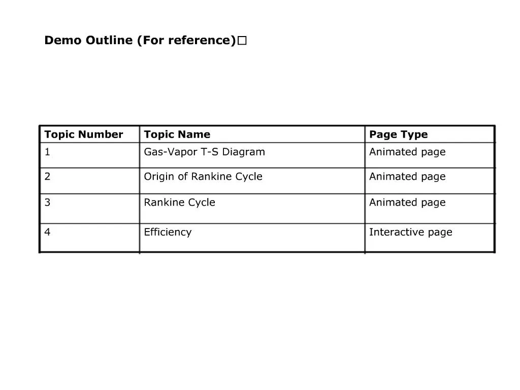
1. STAM Interactive Solutions
4. Voice Over:
An important aspect that lead to modification of Carnot Cycle is the design of practical heat engines. Thus Rankine Cycle is a modified Carnot Cycle.
Click start.
Voice Over:
An important aspect that lead to modification of Carnot Cycle is the design of practical heat engines. Thus Rankine Cycle is a modified Carnot Cycle.
Click start.
5. Voice Over:
The dew-point of a gas-vapor mixture is the temperature at which the vapor condenses when cooled at constant pressure.
The line on a T-S diagram represents the phase-change boundary, depending on the Pressure. That is, each point on the curve is a point where the vapor condenses at a given pressure. Varying the pressure gives you many points that make up the curve.
To the right of the curve, it's all vapor. To the left of the curve, it's all liquid. In between, it's a mix of vapor and liquid.
Visual Guidelines:
Animate the curve first.
Fade in the pressure lines on the curve & flash the intersecting points of the pressure lines with the curve.
Visually show that the right side shape of the curve is vapor & left side shape of the curve is the liquid state. The middle part should be a mix of both liquid and vapor.Voice Over:
The dew-point of a gas-vapor mixture is the temperature at which the vapor condenses when cooled at constant pressure.
The line on a T-S diagram represents the phase-change boundary, depending on the Pressure. That is, each point on the curve is a point where the vapor condenses at a given pressure. Varying the pressure gives you many points that make up the curve.
To the right of the curve, it's all vapor. To the left of the curve, it's all liquid. In between, it's a mix of vapor and liquid.
Visual Guidelines:
Animate the curve first.
Fade in the pressure lines on the curve & flash the intersecting points of the pressure lines with the curve.
Visually show that the right side shape of the curve is vapor & left side shape of the curve is the liquid state. The middle part should be a mix of both liquid and vapor.
6. Voice Over:
All heat engines which convert heat / thermal energy to mechanical energy require a working fluid. This working fluid absorbs energy from one region and delivers it as mechanical work to another region. The Carnot cycle is the most efficient way to do this.
If the working fluid can change phase, as with water/steam, look at the Carnot Cycle T-S diagram shown for this fluid.
If we use the Carnot cycle, point 1 is a mix of steam and water.
This mix of a vapor and liquid is hard to pump � the mechanical design of a pump is difficult, since the objective is to go from point 1 to point 2. Designing a pump that can start with a vapor-liquid gas mix and deliver a liquid is hard.
Hence we prefer to go from point 1 along the horizontal line till we touch the phase-boundary curve, and then from here to point 2.
Similarly, we go from 3 to 4 along the curve and then horizontally, instead of vertically.
Visual Guidelines:
Trace the path of the Rankine cycle as show in the narration.Voice Over:
All heat engines which convert heat / thermal energy to mechanical energy require a working fluid. This working fluid absorbs energy from one region and delivers it as mechanical work to another region. The Carnot cycle is the most efficient way to do this.
If the working fluid can change phase, as with water/steam, look at the Carnot Cycle T-S diagram shown for this fluid.
If we use the Carnot cycle, point 1 is a mix of steam and water.
This mix of a vapor and liquid is hard to pump � the mechanical design of a pump is difficult, since the objective is to go from point 1 to point 2. Designing a pump that can start with a vapor-liquid gas mix and deliver a liquid is hard.
Hence we prefer to go from point 1 along the horizontal line till we touch the phase-boundary curve, and then from here to point 2.
Similarly, we go from 3 to 4 along the curve and then horizontally, instead of vertically.
Visual Guidelines:
Trace the path of the Rankine cycle as show in the narration.
7. Voice Over:
There are four processes in the Rankine Cycle:
The working fluid is pumped from low to high pressure, as the fluid is a liquid at this stage the pump requires little input energy.
The high pressure liquid enters a boiler where it is heated at constant pressure by an external heat source to become a dry saturated vapor.
The dry saturated vapor expands through a turbine, generating power. This decreases the temperature and pressure of the vapor, and some condensation may occur.
The wet vapor then enters a condenser where it is condensed at a constant pressure and temperature to become a saturated liquid.
The other main difference between the Rankine and Carnot cycles is the fact that heat is added under constant-pressure, not constant-temperature. The latter is assumed for a Carnot cycle. This is because the Rankine cycle involves pumping a liquid.
For these reasons, Rankine cycle is a �practical� Carnot cycle.
Visual Guidelines:
In sync with the first 4 narrations animate the particle/arrow tracing the graph in sync with fluid movement on the left side image. Also show a pipe like structure for the cycle 1-2-3-4 with Red & Blue gradient. Red representing when temperature is raised & blue representing when temperature is reduced.Voice Over:
There are four processes in the Rankine Cycle:
The working fluid is pumped from low to high pressure, as the fluid is a liquid at this stage the pump requires little input energy.
The high pressure liquid enters a boiler where it is heated at constant pressure by an external heat source to become a dry saturated vapor.
The dry saturated vapor expands through a turbine, generating power. This decreases the temperature and pressure of the vapor, and some condensation may occur.
The wet vapor then enters a condenser where it is condensed at a constant pressure and temperature to become a saturated liquid.
The other main difference between the Rankine and Carnot cycles is the fact that heat is added under constant-pressure, not constant-temperature. The latter is assumed for a Carnot cycle. This is because the Rankine cycle involves pumping a liquid.
For these reasons, Rankine cycle is a �practical� Carnot cycle.
Visual Guidelines:
In sync with the first 4 narrations animate the particle/arrow tracing the graph in sync with fluid movement on the left side image. Also show a pipe like structure for the cycle 1-2-3-4 with Red & Blue gradient. Red representing when temperature is raised & blue representing when temperature is reduced.
8. Voice Over:
Vary the T1 & T3 temperatures to calculate the efficiency.
Voice Over after the animation:
You can check your understanding on this topic by taking a small quiz. Click the Quiz button on the top right corner of the window.
Visual Guidelines:
Allow the user to change T1 & T3 within the limits specified. Also visually indicate the same on the graph. Values of T2 & T4 will change according to the following equations:
Also show the useful work that is the area enclosed by the curve 1-2-3-4 in different color & the entire work under the 2-3 curve & the x-axis in different color. The increase/decrease in efficiency should be proportional to the increase/decrease in the area 1-2-3-4.
At the end of the animation, change the instruction to: �You can repeat the exercise or Click the Quiz button.�
Voice Over:
Vary the T1 & T3 temperatures to calculate the efficiency.
Voice Over after the animation:
You can check your understanding on this topic by taking a small quiz. Click the Quiz button on the top right corner of the window.
Visual Guidelines:
Allow the user to change T1 & T3 within the limits specified. Also visually indicate the same on the graph. Values of T2 & T4 will change according to the following equations:
Also show the useful work that is the area enclosed by the curve 1-2-3-4 in different color & the entire work under the 2-3 curve & the x-axis in different color. The increase/decrease in efficiency should be proportional to the increase/decrease in the area 1-2-3-4.
At the end of the animation, change the instruction to: �You can repeat the exercise or Click the Quiz button.�
10. Feedback when option 3 is selected:
That�s correct.
A Rankine Cycle is a modification of the Carnot cycle that results in lower efficiency but yields a design that is practical.
Feedback when any other option is selected:
Incorrect.
A Rankine Cycle is a modification of the Carnot cycle that results in lower efficiency but yields a design that is practical.Feedback when option 3 is selected:
That�s correct.
A Rankine Cycle is a modification of the Carnot cycle that results in lower efficiency but yields a design that is practical.
Feedback when any other option is selected:
Incorrect.
A Rankine Cycle is a modification of the Carnot cycle that results in lower efficiency but yields a design that is practical.
11. Feedback when option 1 is selected:
That�s correct.
Rankine cycle involves a closed cycle.
Feedback when any other option is selected:
Incorrect.
Rankine cycle involves a closed cycle.Feedback when option 1 is selected:
That�s correct.
Rankine cycle involves a closed cycle.
Feedback when any other option is selected:
Incorrect.
Rankine cycle involves a closed cycle.
12. Feedback when option 4 is selected:
That�s correct.
The phase of the Rankine Cycle that involves pumping the working fluid is isobaric, and uses less energy than an isothermal process would because a liquid is being pumped.
Feedback when any other option is selected:
Incorrect.
The phase of the Rankine Cycle that involves pumping the working fluid is isobaric, and uses less energy than an isothermal process would because a liquid is being pumped.Feedback when option 4 is selected:
That�s correct.
The phase of the Rankine Cycle that involves pumping the working fluid is isobaric, and uses less energy than an isothermal process would because a liquid is being pumped.
Feedback when any other option is selected:
Incorrect.
The phase of the Rankine Cycle that involves pumping the working fluid is isobaric, and uses less energy than an isothermal process would because a liquid is being pumped.
13. Feedback when option 1 is selected:
That�s correct.
To increase the efficiency of the Rankine Cycle the pressure in the boiler should be raised and the temperature in the condenser should be lowered.
Feedback when any other option is selected:
Incorrect.
To increase the efficiency of the Rankine Cycle the pressure in the boiler should be raised and the temperature in the condenser should be lowered.
Feedback when option 1 is selected:
That�s correct.
To increase the efficiency of the Rankine Cycle the pressure in the boiler should be raised and the temperature in the condenser should be lowered.
Feedback when any other option is selected:
Incorrect.
To increase the efficiency of the Rankine Cycle the pressure in the boiler should be raised and the temperature in the condenser should be lowered.
14. Feedback when option 1 is selected:
That�s correct.
The most common working fluid encountered in Rankine-Cycle based machines is water or steam.
Feedback when any other option is selected:
Incorrect.
The most common working fluid encountered in Rankine-Cycle based machines is water or steam.Feedback when option 1 is selected:
That�s correct.
The most common working fluid encountered in Rankine-Cycle based machines is water or steam.
Feedback when any other option is selected:
Incorrect.
The most common working fluid encountered in Rankine-Cycle based machines is water or steam.