Download
1 / 39
390 likes | 476 Views
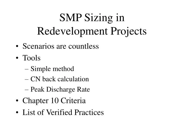
SMP Sizing in Redevelopment Projects. Scenarios are countless Tools Simple method CN back calculation Peak Discharge Rate Chapter 10 Criteria List of Verified Practices. Justification. Site Description Total area = 4 acres Disturbed are = 1 acre Impervious area = .6 acre

E N D
SMP Sizing in Redevelopment Projects • Scenarios are countless • Tools • Simple method • CN back calculation • Peak Discharge Rate • Chapter 10 Criteria • List of Verified Practices
Justification Site Description • Total area = 4 acres • Disturbed are = 1 acre • Impervious area = .6 acre • Precipitation = 1” • Storm Type 2 • Justification • Sizing and SMPs selection • 4 scenarios
Bethlehem, NY • Site information • approximately 29.2% Imp • florist, green houses, parking, planting beds • Proposed development • 54% impervious • condominium complex, 9 buildings and 4 covered garages • Constraints • relocating a sanitary sewer • maintaining setbacks • Proposed practice • CDS units • Underground storage
Scenario 1 • Reconstruction of existing impervious area not exceeding footprint. • Selected Practice: Reduction of Impervious area by 25% • Plan appropriately • Document footprint reduction • Ensure adequate infiltration • Soil amendment • Decompaction
Redevelopment Project with an Existing Detention Pond Keep the detention pond Address WQ treatment
< < WQv Calculation –2100% Impervious Reduce upstream drainage and control an area that is all impervious.
Scenario 2 • Reconstruction of existing impervious area not exceeding footprint. • Selected Practice: Infiltration Trench • Calc. WQv x 25% • Locate sub-catchment & diversion structure • Check feasibility & limitations • Document maintenance plan, etc.
Site DescriptionEddy Greenhouses Nursing facility in Cohoes Area encompass 22 acres Northwestern portion of the property undeveloped (wetlands) Remainder is buildings and parking areas Existing impervious area 8.29 acres Proposed construction 16 Greenhouses New construction 7.8 acres Reconstruction 6.17 acres
Redevelopment Project with an Existing Detention Pond May modify the pond to meet pond design standards
Proposed PlanEddy Greenhouses Reduce impervious area by 25% Design a P-1 Pond Maintain existing water quantity controls in pond Provide treatment for all the new disturbance Provide treatment for a portion of the existing imperviousness Allow sheet flow for ½ of the site that did not have detention in existing condition Did not restore soil property Increase HSG for new pervious area
Scenario 3 • Reconstruction of existing impervious area not exceeding footprint. • Selected Practice: Hydrodynamic System • Back calc. CN • If only imp. Connected, CN = 98 • Define flow rate • Locate sub-catchment, flow splitter • Look up the corresponding model from table 1 • Check all the requirements for suitability of the practice, feasibility, limitations (head, soil, separation distance, etc.) • Document calculation method, manufacturer’s recommendation, maintenance plan, etc.
Equations WQv = [PRvA]/12 Rv=.05+.009*I I = imperviousness P= precipitation (inch) A= area
Hydrodynamic SystemsVortechs System http://www.dec.ny.gov/chemical/29089.html
Alternative PracticesRain Garden WQv £ VSM + VDL + (DP x ARG) VSM = ARG x DSM x nSM VDL (optional) = ARG x DDL x nDL where: VSM = volumeof the soil media [cubic feet] VDL = volumeof the drainage layer [cubic feet] ARG = rain garden surface area [square feet] DSM = depthof the soil media, typically 1.0 to 1.5 feet [feet] DDL = depthof the drainage layer, typically .05 to 1.0 feet [feet] DP = depthof ponding above surface, maximum 0.5 feet [feet] nSM = porosity of the soil media (≥20%) nDL = porosity of the drainage layer (≥40%) WQv = Water Quality Volume [cubic feet], as defined in Chapter 4 of the New York Stormwater Management Design Manual
Redevelopment Project with Increased Footprint Porous Pavement Green Roof