Download
1 / 16
300 likes | 1.05k Views
Aero-thermodynamic design of JAXA’s hypersonic passenger aircraft. Atsushi UENO and Hideyuki TAGUCHI Japan Aerospace Exploration Agency. 1st International Symposium: “Hypersonic flight: from 100.000 to 400.000 ft ” Rome, Italy 30 June, 2014. Contents. Hypersonic research at JAXA

E N D
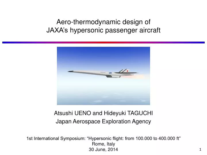
Aero-thermodynamic design of JAXA’s hypersonic passenger aircraft Atsushi UENO and Hideyuki TAGUCHI Japan Aerospace Exploration Agency 1st International Symposium: “Hypersonic flight: from 100.000 to 400.000 ft” Rome, Italy 30 June, 2014
Contents • Hypersonic research at JAXA • R&D roadmap • Baseline configuration defined by MDO • Aerothermodynamic design • Evaluation of aerodynamic heating • Comparison between CFD and WTT • Brief introduction of TPS design • Hikari project(Europe-Japan Collaboration) • Brief introduction of Hikari’s results • Evaluation of hypersonic engine performance • Summary
1. Hypersonic research at JAXA • Hypersonic research at JAXA HypersonicIntegrated ControlExperiment HIMICO Balloon-based Operation Vehicle HypersonicTechnology Experiment HYTEX TSTO HypersonicBusinessJet HypersonicTransport Mach 2 Mach5 Mach 5 Mach 0 ~ 5 SmallPCTJ(Mach2) SmallPCTJ(Mach5) MediumPCTJ LargePCTJ JAXA’s R&D Roadmap on Hypersonic Transport Aircraft Variable intakePre-coolerCore engineVariable nozzle Pre-Cooled TurboJet Engine (PCTJ)
1. Hypersonic research at JAXA • Hypersonic transport • 100 passengers • Mach 5 / Altitude 25 km • 2 hours from Tokyo to Los Angeles • Use existing airports Engine cut-off Altitude [km] Const. dynamic pressure 3. Cruise (around Mach 5) Mach 2. Acceleration 4. Deceleration (90min., 7600km) 1. Take-off (10 min., 700km) (10min., 400km) 5. Landing Pacific ocean Mission profile
1. Hypersonic research at JAXA • Baseline configuration • Multidisciplinary design optimization Design variables Weight Shape Weight Inlet area Shape Aero. force Aero. Thrust SFC Optimization Propulsion AoA Mach Altitude Mach Mission Objective function Constraint function Fuel weight Fuel tank Cabin Fuel tank Baseline configuration
2. Aero-thermodynamic design • Evaluation of Aerodynamic heating rate • In MDO, aero. heating was not taken into account. • TPS weight was estimated using empirical relation. • HASA, NASA-Contractor Report 182226 • CFD and wind tunnel test (WTT) were conducted to evaluate aero. heating. CFD (WTT condition) (Flight condition) WTT Validation Aero. heating TPS design
2. Aero-thermodynamic design • CFD analysis • Navier-Stokes analysis • JAXA’s UPACS code • Equation: RANS • Flux discretization: AUSMDV (3rd order) • Turbulent model: Spalart-Allmaras • Number of points: 15 million • Flow condition: • Wind tunnel condition • T0 = 700 [K], M = 5, AoA = 5 [deg] • Re = 1.7x10⁶ (P0=1.0 [MPa]), Laminar • Re = 7.1x10⁶ (P0=1.5 [MPa]), Turbulent • Tw = 303 [K], Isothermal wall • Flight condition • h = 24.2 [km], M = 5, AoA = 5 [deg] • Re = 4.0x10⁸, Turbulent • Tw = 823 [K], Isothermal wall Validation TPS design
2. Aero-thermodynamic design • Wind tunnel test • JAXA HWT1
2. Aero-thermodynamic design • Wind tunnel test • Wind tunnel model Temperature semi-infinite, 1D heat equation Aerodynamic heating sphere (Φ1mm) Boundary layer trip 0.25% model, L=220mm Fuselage + Wing + V-tail (qw on all components in laminar B.L.) 0.74% model, L=643mm Fuselage (qw in turbulent B.L.) Wind tunnel model
2. Aero-thermodynamic design • Result of WTT • Result of 0.25% model (Laminar boundary layer) • Wind tunnel test Aerodynamic heating (M = 5, AoA = 5 [deg], Upper surface) Aerodynamic heating on all components was measured. Large aerodynamic heating due to separated vortex was observed.
2. Aero-thermodynamic design • Comparison between CFD and WTT • Result of 0.25% model (Laminar boundary layer) Upper surface (WTT) Upper surface(CFD) qw upper Nose lower qw Lower surface (WTT) • semi-infinite,1D heat equation is not correct. • Overestimation in WTT Lower surface (CFD) CFD agrees with wind tunnel test qualitatively except in region where thickness of model is thin. Distribution of Stanton number at AoA=5deg.
2. Aero-thermodynamic design • Comparison between CFD and WTT • Result of 0.74% fuselage model (Turbulent boundary layer) Upper surface (WTT) Boundary layer trip Camera #1 Camera #2 Upper surface(CFD) Distribution of Stanton number at AoA=5deg. Boundary layer transition was observedbehind boundary layer trip. High aero. heating due to separated vortex was observed also in turbulent B.L.
2. Aero-thermodynamic design • Comparison between CFD and WTT • Result of 0.74% fuselage model (Turbulent boundary layer) Boundary layer trip Camera #1 Center of fuselage CFD WTT Camera #2 Aero. heating differs in the region where separated vortex is attached. CFD shows larger aero. heating. Center of vortex (y/L=0.028) CFD WTT
2. Aero-thermodynamic design • TPS design based on CFD result High heating rate (qw: ~ 100kW/m2) High heating rate (qw: ~ 100kW/m2) Upper Lower Cabin (qw: 5 ~ 15kW/m2) Cryogenic tank (qw: 5 ~ 20kW/m2) Thin wing (qw: 5 ~ 30kW/m2) CFD result at flight condition Super alloy (Inconel) honeycomb should be applied in the region where aerodynamic heating is large (e.g., nose and leading edge). Ti multi-wall can be applied in the region where qw is about 20kW/m2. • Summary • Results of wind tunnel test and CFD agreed qualitatively. • CFD showed larger aerodynamic heating in the region where separated vortex is attached. • Different turbulent model should be tested in the future. • TPS was designed based on aerodynamic heating obtained by CFD. • TPS material was selected.
3. Hikari project Europe-Japan“HIKARI”Collaboration Objectives: Marketanalysis,EnvironmentalImpactAssessment, AircraftSystemsStudy,Propulsion,CommonR&DRoadmap TaskofJAXA: PerformanceevaluationofHypersonicPre-CooledTurbojetEngine Status: Mach4experimenthasbeensuccessfullyconducted. PerformancemapwillbeprovidedtoresearchpartnersinAugust. Mach4DirectConnectTest • High TemperatureStructure • Mach 4 Operation Mach4WindTunnelTest • Starting Sequence • Heat Structure of Variable Mechanism 2005 HypersonicPre-CooledTurbojetEngine(JAXA) 2010 2015 2020 2025
4. Summary • Hypersonic passenger aircraft was studied using MDO technique. • Baseline was defined. • Aerodynamic heating rate was evaluated by both CFD and WTT. • CFD and WTT showed qualitative agreement. • TPS was designed based on aerodynamic heating rate obtained by CFD. • Results from Hikari project was briefly introduced. • Future works: • Plan for experimental vehicle with small PCTJ flying at Mach 5.