Download
1 / 30
300 likes | 450 Views
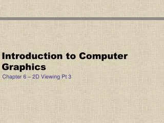
SI23 Introduction to Computer Graphics. Lecture 12 – 3D Graphics Transformation Pipeline: Projection and Clipping. viewing co-ords. Projection Transform’n. mod’g co-ords. world co-ords. Viewing Pipeline So Far. From the last lecture, we now should understand the viewing pipeline.

E N D
SI23Introduction to Computer Graphics Lecture 12 – 3D Graphics Transformation Pipeline: Projection and Clipping
viewing co-ords Projection Transform’n mod’g co-ords world co-ords Viewing Pipeline So Far • From the last lecture, we now should understand the viewing pipeline Viewing Transform’n Modelling Transform’n The next stage is the projection transformation….
Perspective and Parallel Projection parallel perspective
yV zV camera camera direction xV Viewing Co-ordinate System • The viewing transformation has transformed objects into the viewing co-ordinate system, where the camera position is at the origin, looking along the negative z-direction
dNP View Volume yV zV near plane far plane camera q xV dFP We determine the view volume by: - view angle, q - aspect ratio of viewplane - distances to near plane dNP and far plane dFP
yV near plane zV camera dNP xV Projection We shall project on to the near plane. Remember this is at right angles to thezV direction, and has z-coordinate zNP = - dNP
yV near plane zV camera Q dNP xV yV zNP zQ zV camera view plane Perspective Projection Calculation zNP looking down x-axis towards the origin
Q yV zNP zQ zV camera view plane Perspective Projection Calculation P By similar triangles, yP / yQ = ( - zNP) / ( - zQ) and so yP = yQ * (- zNP) / ( - zQ) or yP = yQ * dNP / ( - zQ) Similarly for the x-coordinate of P: xP = xQ * dNP / ( - zQ)
Using Matrices and Homogeneous Co-ordinates • We can express the perspective transformation in matrix form • Point Q in homogeneous coordinates is (xQ, yQ, zQ, 1) • We shall generate a point H in homogeneous co-ordinates (xH, yH, zH, wH), where wH is not 1 • But the point (xH/wH, yH/wH, zH/wH, 1) is the same as H in homogeneous space • This gives us the point P in 3D space, ie xP = xH/wH, sim’ly for yP
xQ yQ zQ 1 xH yH zH wH 1 0 0 0 0 1 0 0 0 0 1 0 0 0 -1/dNP 0 Transformation Matrix for Perspective = Thus in Homogeneous co-ordinates: xH = xQ; yH = yQ; zH = zQ; wH = (-1/dNP)zQ In Cartesian co-ordinates: xP = xH / wH = xQ*dNP/(-zQ); yP similar; zP = -dNP = zNP
OpenGL • Perspective projection achieved by: gluPerspective (angle_of_view, aspect_ratio, near, far) • aspect ratio is width/height • near and far are positive distances
Vanishing Points • When a 3D object is projected onto a view plane using perspective, parallel lines in object NOT parallel to the view plane converge to a vanishing point vanishing point one-point perspective projection of cube view plane
One-point Perspective This is: Trinity with the Virgin, St John and Donors, by Mastaccio in 1427 Said to be the first painting in perspective
Two-point Perspective Edward Hopper Lighthouse at Two Lights -see www.postershop.com
Orthographic parallel projection has view plane perpendicular to direction of projection Oblique parallel projection has view plane at an oblique angle to direction of projection Parallel Projection - Two types P1 P1 P2 P2 view plane view plane We shall only consider orthographic projection
yV near plane zV dNP xV Parallel Projection Calculation looking down x-axis Q P yV zQ zNP zV view plane yP = yQ similarly xP= xQ
Parallel Projection Calculation • So this is much easier than perspective! • xP = xQ • yP = yQ • zP = zNP • The transformation matrix is simply 1 0 0 0 0 1 0 0 0 0 zNP/zQ 0 0 0 0 1
dNP View Frustum and Clipping yV zV near plane far plane camera q xV dFP The view volume is a frustum in viewing co-ordinates - we need to be able to clip objects outside of this region
Clipping to View Frustum • It is quite easy to clip lines to the front and back planes (just clip in z).. • .. but it is difficult to clip to the sides because they are ‘sloping’ planes • Instead we carry out the projection first which converts the frustum to a rectangular parallelepiped (ie a cuboid) Retain the Z-coord
Clipping for Parallel Projection • In the parallel projection case, the viewing volume is already a rectangular parallelepiped far plane view volume near plane zV
Normalized Projection Co-ordinates • Final step before clipping is to normalize the co-ordinates of the rectangular parallelepiped to some standard shape • for example, in some systems, it is the cube with limits +1 and -1 in each direction • This is just a scale transformation • Clipping is then carried out against this standard shape
view’g co-ords proj’n co-ords mod’g co-ords world co-ords normalized projection co-ordinates Viewing Pipeline So Far • Our pipeline now looks like: NORMALIZATIONTRANSFORMATION
And finally... • The last step is to position the picture on the display surface • This is done by a viewport transformation where the normalized projection co-ordinates are transformed to display co-ordinates, ie pixels on the screen
view’g co-ords proj’n co-ords mod’g co-ords world co-ords normalized projection co-ordinates Viewing Pipeline - The End • A final viewing pipeline is therefore: device co-ordinates DEVICETRANSFORMATION