Download
1 / 48
490 likes | 925 Views
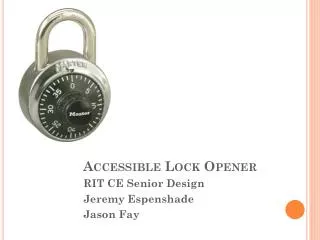
Combination Lock Opener. Bill Samore Brian Elies Mike Arthur. Intro, Features, Cracking the MasterLock ®, Stepper Motor & Driver- Bill Photo Sensors, Flywheel, Solenoid, H-Bridge- Brian PIC, Keypad, 7-Segment Display, Gate Detection & Opening the Lock- Mike

E N D
Combination Lock Opener Bill Samore Brian Elies Mike Arthur
Intro, Features, Cracking the MasterLock®, Stepper Motor & Driver- Bill Photo Sensors, Flywheel, Solenoid, H-Bridge- Brian PIC, Keypad, 7-Segment Display, Gate Detection & Opening the Lock- Mike Time to Open Lock, Ethics- Bill Testing and Conclusion- Brian Questions Talk Outline
Introduction Many people forget the combination to their lock and then need to buy a new one. If it took a person 15 seconds to enter a combination it would take 11 days 2 hours and 40 minutes to try all 64,000 possible combination. Our combination lock opening device narrows the possible combinations down to 80, and then tries each one of those to discover the correct combination.
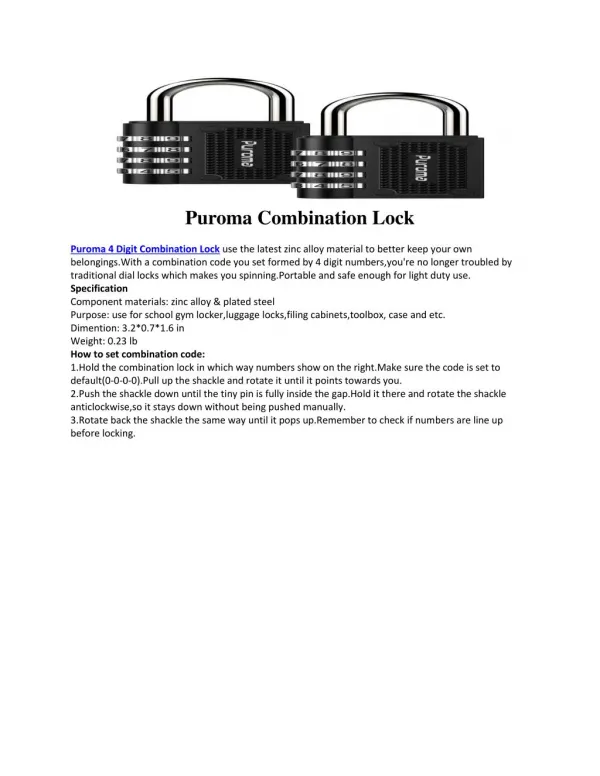
Features • Works with MasterLock® combination locks • Many lock picking techniques will either destroy the lock or not reveal the combination • Our device displays the combination to the lock once it opens the lock • A user friendly device that is completely automated
Cracking the MasterLock ® • Find the internal gates • To locate the gates pull up on the latch of the lock while rotating the dial- it will get stuck between two numbers or half numbers. Record the midpoint of where the dial sticks.
Repeat this process all the way around the lock. There will be 12 gates. 5 of the gates will be whole numbers and 7 will be half numbers. The last digit of one of the whole numbers will be different than the rest: This is the 3rd number of the combination! Cracking the MasterLock ® Gates from one of our Locks: 3 6.5 9.5 13 16.5 20 23 26.5 29.5 33 36.5 39.5 3rd number of the combo!
Take the 3rd number of your combination and divide it by 4. Take the remainder and record it- this is the first possibility for the first number in the combination. The other possible first numbers of the combination are found by adding 4 to this number until the highest possible number (39) is reached. Cracking the MasterLock ® Our example continued: 3rd number of combination = 20 20 % 4 = 0 Possible 1st numbers of the combination: 0,4,8,12,16,20,24,28,32,36
Take the remainder from earlier. If it was a 0 or 1 add two to it. If it was a 3 or 4 subtract two from it. This is the first possibility for the second number in the combination. The other possible second numbers to the combination are found by adding 4 to this number until the highest possible number (39) is reached. Cracking the MasterLock ® Our example continued: Remainder from before = 0 0 + 2 = 2 Possible 2nd numbers of the combination: 2,6,10,14,18,22,26,30,34,38
We now have 10X10 = 100 possible combinations. However all combinations must be either low-high-low or high-low-high this eliminates 20 possible combinations There are 100-20= 80 possible combinations Cracking the MasterLock ® Our example continued: 0-30-20 is low-high-low so it is possible 20-10-20 Is high low high so it is possible 0-10-20 is neither low-high-low nor high-low-high so it is notpossible and we do not need to try it
Stepper Motor Keypad Light Sensors 7-SegDisplay Transformer Flywheel Solenoid Motor PIC H-Bridge
The Stepper Motor • Detent Torque 200 g-cm (no current is flowing to the motor) • Holding Torque 1000 g-cm (current is flowing to the motor) • Draws an average of 6 v and 300 mA • Power dissipated = IV = 1.8 watt
The Stepper Motor • Has step angle 1.8º • Motor controller has half stepping mode so we can turn the motor in .9º increments • There are 40 numbers on the lock and we need to be able to tell the difference between half-numbers therefore we need 360º/(40*2)= 4.5º • 4.5º/.9º = 5 half stepper motor steps to turn 1 half number on the lock
Photo Sensors • 3 sensor total • Each consist of a photo diode and a photo BJT • The sensors use the 5 volt supply • Dissipate .13 watts of power each
Concept of Reflective Photo Sensing White Surface Black Surface
Photo Sensor Placement Flywheel (Top) Whole Number divisions 20 black and 20 white Half Number divisions 40 black and 40 white
Photo Sensor Placement cont. Flywheel (Bottom) The black mark is aligned with zero on the lock
Solenoid Opens the lock Assists with Gate detection Connected to the latch of the lock with a zip tie The lock is held in place via an indentation in the aluminum cross bar
H-Bridge Function • H-Bridge acts as interface between solenoid and PIC • 2 PIC inputs • PIC does not allow both to be High
H-Bridge Analysis Ip1=Ip4=5ma Ip2=Ip3=0ma Is=4.15A Vs=11.2V Ps=46.48Watt
H-Bridge Analysis cont. Ip1=Ip4=0ma Ip2=Ip3=26ua Is=-.7A Vs=-1.9V Ps=1.33Watt
Summary of PIC • PIC is main control unit for the device • Receives user input from keypad • Outputs to 7-segment display • Controls Solenoid and Stepper Motor • Receives status data from sensors
Keypad • Keypad is users interface to the device • Allows user to input a combination • If user hits enter, device begins to unlock lock • Input capability also useful in testing
Seven Segment Display • Provides feedback to user from the device • Displays the current input by the user • Ultimately displays the correct combination of the lock • Feedback useful in testing of device
Gate Detection • After enter is pressed, unlocker enters gate detection mode • Rotates half steps and reads from the sensors as to whether or not the lock is stuck • If lock is stuck, rotates to zero to calibrate, displays where locks got stuck, and then returns • Three rotations to obtain data
PIC is programmed to decide from the three trials what the most likely gates are -based on the results of the trials and known data of where gates often are From these gates, the PIC identifies the one that is different from the other gates as the last number Displays last number after calculated Last number Calculations
Inputting a number and hitting enter twice will enter lock opening mode Device tries all 80 possible combinations with that last number – displays combination as it is trying it If this device were to be marketed, these and all other break points would removed Attempts to open lock
Sample gates can be hard coded and the device is able to engage in a mode where it will determine the most likely gates from the hard coded data Useful to confirm that correct gate locations are being determined Testing – Finding Most Likely Gates
Acceleration Function • If the clock speed is too fast, motor gets stuck • In order to increase the speed that the lock opens an accelerating clock is outputted to the stepper motor • Accelerated from 24 ms per step to 6 ms per step
Time to crack lock 1.) Find all of the internal gates. This takes about 6 min 2.) Try all 80 of the possible combinations. It takes an average of 17 seconds to try 1 combination or about 23 min to try all 80. Therefore the expected time for step 2 is 11.5 minutes. Total Expected Time = 6 + 11.5 = 17.5 min
Reliability • Error rate for gate detection is 25% • We use 3 attempts to find each gate reducing the error drastically • Device recalibrates (re-zeros) after every attempt to find a gate and after every combination it inputs also improving reliability
Sensor readings Combination entry Gate Detection Mass Combination entry Combination Found Testing
Our device should only be used to find the combination to one’s own lock. Not to break into someone else’s! It would be very difficult to fit a lock into our device if it was attached to anything such as a locker Ethical Considerations
Conclusion Strengths Saves time and money Can find combination to any Master Lock® Weakness Time consuming to change lock Gate detection unreliable Future New software for other brands of locks. Reduced time to crack lock Possible Customers Stores that sell locks Gym/High School Locker rooms
Credits • Alex Spektor • Professor P. Scott Carney • People in the parts shop • Scott from the machine shop • Instructional video from youtube.com • Opening Combination Locks by Carl Black
Mode: M-82 manufactured: Pontiac Coil Inc. Exerts a force of about 75 ounces at a distance of .25 inches. a latching solenoid Solenoid Specification
Power Supply for the Solenoid • The solenoid draws approximately 4.15 amps • KRII150M 12V 12A power supply supplies power • The voltage of the supply was increased to 13.6V.