Download
1 / 36
360 likes | 380 Views
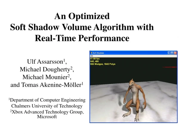
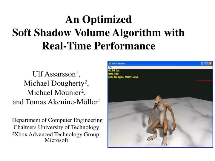
An Optimized Soft Shadow Volume Algorithm with Real-Time Performance. Ulf Assarsson 1 , Michael Dougherty 2 , Michael Mounier 2 , and Tomas Akenine-Möller 1 1 Department of Computer Engineering Chalmers University of Technology 2 Xbox Advanced Technology Group, Microsoft.

E N D
An Optimized Soft Shadow Volume Algorithm withReal-Time Performance Ulf Assarsson1, Michael Dougherty2, Michael Mounier2, and Tomas Akenine-Möller1 1Department of Computer Engineering Chalmers University of Technology 2Xbox Advanced Technology Group,Microsoft
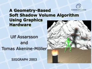
Soft Shadow Volume Algorithm • Ulf Assarssonand Tomas Akenine-Möller. “A Geometry-Based Soft Shadow Volume Algorithm Using Graphics Hardware” SIGGRAPH 2003, Tuesday, June 29, ~4.30 pm • Area light sources • Simple volumetric light sources • Textures and short video textures as lights
This Paper • Presents new optimizations • Real-Time performance for: • area light sources • spherical light sources • gray scale textures
Two different light source types: point source area source umbra penumbra umbra Hard vs. soft shadows
Optimizations • Culling • Only run pixel shader for points inside the wedge • Tighter wedges around the penumbra • 1.2 – 2 times speedup • Optimized Pixel Shader • Previously ~250 instructions, • now ~60 instructions.
Artifacts and a Solution Two major approximations: • Assume constant silhouette • I.e., one single silhouette as seen from all locations of the light area. • Ignore overlap between occluders
Worst Case Example One light source 1024 point lights
For better quality, use 2x2 area lights (2x2 does not cost 4 times as much!) One light source 2x2 light sources 1024 point lights
For better quality, use 2x2 area lights (2x2 does not cost 4 times as much!) One light source 2x2 light sources 1024 point lights One light source 1024 point lights
For better quality, use 2x2 area lights (2x2 does not cost 4 times as much!) One light source 2x2 light sources 1024 point lights One light source 2x2 light sources 3x3 light sources 1024 point lights
Optimized Shaders • We wrote two optimizated shaders, one for a sperical light source and one for a planar light source • Both shaders follow approximatly the same steps • Transform the silhouette edge to projected space • Clip the edge and do a perspective divide • Calculate the coverage using the two resulting 2D points • “Split” the coverage and add it to the visibility mask
Transform the Silouhette Edge to Projection Space • Projection space is defined as the point to be shaded at the origin and the light center located on the z axis at z = 1
Clip Edge and Do a Perspective Divide • Clipping is done in homogenous space • The square light shader clips edge to planes in homogenous space. • The spherical light shader solves the equation of an intersection with a cone and line in homogenous space. • The perspective divide is simply x/z and y/z.
Calculate Coverage Using the Resulting 2D Points • The angles between A and the x axis (0) and B and the x axis (1) are calculated by looking up the x and y of the vectors in a cube map that implements atan2. • 0 and 1are used as coordinates to lookup in a 2D texture that returns the area defined by the intersection of the area swept by the rays from the light center through the projected points and the square or circle area. • ½ the cross product of A and B is subtracted from the area overestimate to give the coverage (shaded in gray).
Split the Coverage and Add it to the Visibility Mask • A 1D texture is used to “split” the coverage value across four 8-bit channels. • The spilt is required to allow for overflow when incrementing the visibility mask. • Positive and negative contributions to the mask are stored separately. • The split values are recombined with a dot product that scales each channel and adds them together • The split and recombine steps could be skipped on hardware that supports blending on greater than 8-bit per channel render targets.
Quality Reference image Our algorithm
Quality Reference image Our algorithm
Quality Small light source Large light source
Quality 512 point lights Our algorithm
Real-Time Demo coded by: Michael Dougherty and Michael Mounier Xbox Advanced Technology Group, Microsoft
Demo Notes • We do a pass to write out the world space xyz. The depth z and screen space x and y could be transformed by the inverse of the view*projection matrix to save bandwidth but we were limited on instruction count. • There was no profiling done on the sample. It may be bound by the massive number of render state changes required to render each wedge half. • On the ATI 9700 • The default clip planes did not provide enough accuracy on clipped texture coordinate values. This caused the sampled world space xyz to be off. User clip planes fixed the problem. • The center plane of each wedge needed to be shared (save vertices and cull order) by both wedge halves in order to avoid artifacts.
Thanks for listening… Questions? More info here: www.ce.chalmers.se/staff/tomasm/soft/


![Real-Time Volume Graphics [03] GPU-Based Volume Rendering](https://cdn2.slideserve.com/4026797/real-time-volume-graphics-03-gpu-based-volume-rendering-dt.jpg)
![Real-Time Volume Graphics [07] Global Volume Illumination](https://cdn2.slideserve.com/4312752/real-time-volume-graphics-07-global-volume-illumination-dt.jpg)
![Real-Time Volume Graphics [06] Local Volume Illumination](https://cdn2.slideserve.com/4770316/real-time-volume-graphics-06-local-volume-illumination-dt.jpg)