Download
1 / 9
120 likes | 384 Views
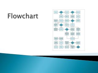
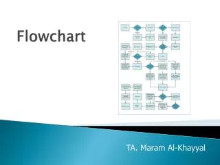
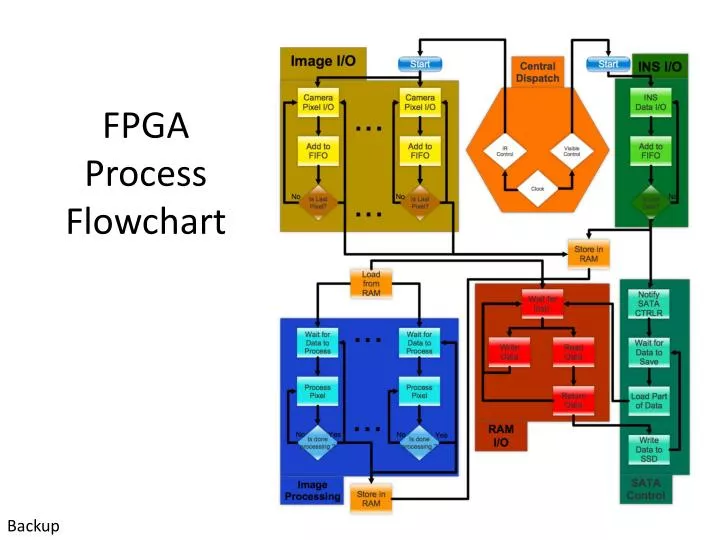
FPGA Process Flowchart. Backup. FPGA Configurability. Basis of configurability Nature of transistor based FPGA Physical limitations Through header on PCB using Xilinx provided development tools. Backup. FPGA Configurability. Customer configurable Configuration languages

E N D
FPGA Process Flowchart Backup
FPGA Configurability • Basis of configurability • Nature of transistor based FPGA • Physical limitations • Through header on PCB using Xilinx provided development tools Backup
FPGA Configurability • Customer configurable • Configuration languages • Knowledge of VHDL/Verilog • Development packages • Xilinx provided development tools • Physical configuration requirements • Connect programmer and download data file, restart board Backup
Processing Elements • FPGA • Transistor based • VHDL/Verilog DSP • CPU based • C Language Backup
Customer Needs • Use Supplied Components • 10MP Visual Camera • IR Camera • 1 of the 2 Inertial Navigation Systems depending on availability • NovAtel OEM Board OEMV3 • NovAtel OEM Board OEMV2 • OEM Camera Processing Board • Interface to single 10Mpixel Camera through proprietary “D3 Camera” connector. • Interface to single Thermal Camera through Camera Link Interface. • Capture 10MP data at 1FPS • Capture the Thermal Camera data synchronized with the 10Mpixel camera. • Capture INS data and store to match corresponding photos. • Accept data from auxiliary external cameras and INS units • Make data overlay and processing possible on-board • Output data from the supplied OEM Board connection for real-time viewing • Store data internally during flight using a SSD SATA drive. • Package must include mounting and space necessary for four cameras. • Package everything (except for the IR camera) to protect it against the environment and to minimize the size. “Everything” Includes: • (4) visual cameras and their lenses • (1) INS sensor • (1) OEM Camera Processing Board • Any other components necessary for operation • Position images for ground observations • Make cameras separable from the processing hardware • Interface package to a light passenger aircraft.
Backup slide: Final Output Color Aerial Photograph IR Camera with INS Data overlay
Customer provided devices • OEM Digital Signal Processing Board • CameraLink® to D3 Conversion Chips • Novatel OEM Board • IMU System • Cameras • (2) Using D3 Connector interface • (1) IR using Camera Link BACKUP SLIDE
Appendix: Radiation • Assumptions: Treat enclosure as a black box • Neglect Convection • Neglect Conduction • Temperature at surface of chassis = temperature inside of chassis • All Power consumed by electronics is output as heat radiating out • = .89 • qc = .5qb
Appendix: Humidity • Dew point temperature is given as: • Constants defined as follows: • Variables: • Td - Dew point (C) • T - Ambient temperature (C) • RH - Relative humidity (%) • m - Temperature range dependant constant (non-dimensional) • Tn - Temperature range dependant constant (C)