Download
1 / 14
150 likes | 568 Views
DESIGN AND CONSTRUCTION OF AN INDUCTION FURNACE (COOLING SYSTEM). Presented by MG THANT ZIN WIN Roll No: Ph.D-M-7. Supervisors : Dr Mi Sanda Mon Daw Khin War Oo. 20th Seminar 10.11.2004.

E N D
DESIGN AND CONSTRUCTION OF AN INDUCTION FURNACE(COOLING SYSTEM) Presented by MG THANT ZIN WIN Roll No: Ph.D-M-7 Supervisors : Dr Mi Sanda Mon Daw Khin War Oo 20th Seminar 10.11.2004
Net Positive Suction Head Available (NPSHA) It depends upon the elevation or pressure of the suction supply friction in the suction line, attitude of the installation, and the vapor pressure of the liquid being pumped. hsp = static pressure head (absolute) applied to the fluid, m or ft hs = elevation difference from the level of fluid in the water tank to the pump inlet, m or ft If pump is below water tank, hs is positive. If pump is above water tank, hs is negative. hf = fraction loss in suction piping, m or ft hvp = vapor pressure of the liquid at the pumping temperature in meters or feet of the liquid
Net Positive Suction Head Required (NPSHR) • It varies with flow, temperature and attitude have no effect. N = required motor speed, rpm Q = the water flow rate of pump, m3/min
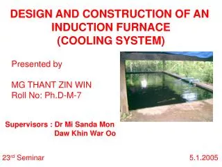
Checking for Suction Performance of Cooling System of UNIDO Induction Furnace Pump GI Pipe 15.6972m Water tank PVC Pipe 3.6576m Fig – Suction line arrangement
Pump Ball valve 0.2032 m Foot valve Water cooling tank Fig – Side view of water cooling tank with pumping station Known data : Capacity to be pumped 0.69 m3/min Required motor speed 2900 rpm Size of all pipes, valves and fittings
Determine the Fraction Losses for GI Pipe where, From Moody diagram, f = 0.0195
Determine the Fraction Losses for PVC Pipe where, From Moody diagram, for smooth pipe f = 0.0139
Absolute pressure = Atmospheric pressure - gage pressure = Atmospheric pressure – water tank Pabs= 101.25 kPa 0 where,
Finally, It may be suitable to use or select a centrifugal pump for cooling system of UNIDO Induction Furnace.