Download
1 / 66
660 likes | 764 Views
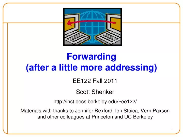
Forwarding (after a little more addressing). EE122 Fall 2011 Scott Shenker http:// inst.eecs.berkeley.edu /~ee122/ Materials with thanks to Jennifer Rexford, Ion Stoica , Vern Paxson and other colleagues at Princeton and UC Berkeley. Agenda. Dealing with address scarcity: DHCP , NAT

E N D
Forwarding(after a little more addressing) EE122 Fall 2011 Scott Shenker http://inst.eecs.berkeley.edu/~ee122/ Materials with thanks to Jennifer Rexford, Ion Stoica, Vern Paxsonand other colleagues at Princeton and UC Berkeley
Agenda • Dealing with address scarcity: DHCP, NAT • Address Aggregation • Conceptual issues • Forwarding
Follow-up from last time • Giving back /8: • That was Stanford, not Berkeley, that gave back a /8 • Original ARPANET: UCLA, UCSB, Stanford, U. of Utah • LBL was involved in ARPANET later, but not Berkeley • Padding fragments? (Offsets are multiples of 8) • Padding not needed! • Early fragments need to be multiples of 8 • Last fragment need not be! Length field not multiple of 8 • Put the leftover bits there…. • Example: break 1303 bytes into 400+400+400+103
Sharing a Block of Addresses • Dynamic Host Configuration Protocol (DHCP) • Configures several aspects of hosts • Most important: assigns temporary address (lease) • Uses DHCP server to do allocation • Multiplexes block of addresses across users • DHCP protocol: • Broadcast a server-discovery message (layer 2) • Server(s) sends a reply offering an address ... host host host DHCP server
Response from the DHCP Server • DHCP “offer” message from the server • Configuration parameters (proposed IP address, mask, gateway router, DNS server, ...) • Lease time (duration the information remains valid) • Multiple servers may respond • Multiple servers on the same broadcast network • Each may respond with an offer • Accepting one of the offers • Client sends a DHCP “request” echoing the parameters • The DHCP server responds with an “ACK” to confirm • … and the other servers see they were notchosen
Dynamic Host Configuration Protocol DHCP discover (broadcast) DHCP server 203.1.2.5 DHCP offer arrivingclient (broadcast) Why all the broadcasts? DHCP request (broadcast) How does DHCP send a broadcast? DHCP ACK (broadcast)
Sending Broadcasts • DHCP is at application layer • Uses UDP transport protocol • IP does not support global broadcasts • And DHCP only wants local broadcast • How to send local broadcast w/o violating layers?
Special-Purpose Address Blocks • Limited broadcast • Sent to every host attached to the local network • Block: 255.255.255.255/32 • Private addresses • By agreement, not routed in the public Internet • For networks not meant for general Internet connectivity • Blocks: 10.0.0.0/8, 172.16.0.0/12, 192.168.0.0/16 • Link-local • By agreement, not forwarded by any router • Used for single-link communication only • Intent: autoconfiguration (especially when DHCP fails) • Block: 169.254.0.0/16 • Loopback • Address blocks that refer to the local machine • Block: 127.0.0.0/8 • Usually only 127.0.0.1/32 is used
Back to DHCP: Uses “Soft State” • Soft state: if not refreshed state will be forgotten • Install state with timer, reset timer when refresh arrives • Delete state if refresh not received when timer expires • Allocation of address is “soft state” (renewable lease) • Why do you “lease” addresses? • Client can release the IP address (DHCP RELEASE) • E.g., “ipconfig /release” at the DOS prompt • E.g., clean shutdown of the computer • But, host might not release the address • E.g., the host crashes (blue screen of death!) • E.g., buggy client software • And you don’t want the address to be allocated forever • So if request isn’t refreshed, server takes address back
DHCP • Allows you to share a set of addresses • As laptops come and go • But does not solve problem when you have many permanent hosts and only one address….
Sharing Single Address Across Hosts • Network Address Translation (NAT) enables many hosts to share a single address • Uses port numbers (fields in transport layer) • Was thought to be an architectural abomination when first proposed, but it: • Probably saved us from address exhaustion • And reflects a modern design paradigm (indirection) • But first, a word about ports….
How does a host handle packets? • Ethernet packet has EtherType field • Which protocol to hand payload to (e.g., IP) • IP has Protocol field • Which protocol to hand payload to (e.g., UDP, TCP) • Transport protocols have port numbers • Which process to hand payload to • Source port and destination port both specified • Well-known ports: services such as HTTP (80), SSH (22) • What is port 17? • Ephemeral ports: for client instances, etc. Why?
src addr src port dest addr 5.6.7.8 1.2.3.4 80 1001 dst port 80 1001 5.6.7.8 1.2.3.4 Network Address Translation (NAT) Before NAT…every machine connected to Internet had unique IP address Server LAN 1.2.3.4 Internet 5.6.7.8 1.2.3.5 Clients
80 1001 5.6.7.8 192.2.3.4 5.6.7.8 1.2.3.4 80 2000 5.6.7.8 192.2.3.4 80 1001 80 2000 5.6.7.8 1.2.3.4 192.2.3.4:1001 1.2.3.4:2000 NAT (cont’d) • Assign addresses to machines behind same NAT • Can be any private address range • e.g. 192.168.0.0/16 • Use port numbers to multiplex single address Server NAT 192.2.3.4 Internet 5.6.7.8 1.2.3.4 192.2.3.5 Clients
80 1001 5.6.7.8 192.2.3.5 5.6.7.8 1.2.3.4 80 2001 5.6.7.8 192.2.3.5 80 1001 80 2001 5.6.7.8 1.2.3.4 192.2.3.4:1001 1.2.3.4:2000 192.2.3.5:1001 1.2.3.4:2001 NAT (cont’d) • Assign addresses to machines behind same NAT • Usually in address block 192.168.0.0/16 • Use port numbers to multiplex single address Server NAT 192.2.3.4 Internet 5.6.7.8 1.2.3.4 192.2.3.5 Clients
NAT: Early Example of “Middlebox” • Boxes stuck into network to delivery functionality • NATs, Firewalls,…. • Don’t fit into architecture, violate E2E principle • But a very handy way to inject functionality that: • Does not require end host changes or cooperation • Is under operator control (e.g., security) • An interesting architectural challenge: • How to incorporate middleboxes into architecture
Review of Addressing • Notation: dotted quad (e.g., 16.45.231.117) • Set of four 8-bit numbers • Structure: (prefix, suffix) • Network component (prefix) • Host component (suffix) • Slash notation: /x means that prefix is x bits long • Addressing schemes: • Original: prefix of length 8 (all addresses in /8s) • Classful: opening bits determined length of prefix E.g., 0 meant /8, 10 meant /16, 110 meant /24, 1110 meant mcast • Classless (CIDR): explicit mask defines prefix
00001100 00000100 00000010 00000001 11111111 11111110 00000000 00000000 CIDR Addressing Use two 32-bit numbers to represent a network location Address + Mask IP Address : 12.4.2.1 IP Mask: 255.254.0.0 Address Mask Network Prefix for hosts
00001100 00000100 00000000 00000000 11111111 11111110 00000000 00000000 CIDR Prefixes Use two 32-bit numbers to represent a network prefix Address + Mask Prefix: 12.4.0.0 IP Mask: 255.254.0.0 Address Mask Network Prefix for hosts Written as 12.4.0.0/15 or 12.4/15
Allocation Done Hierarchically • ICANN gives large blocks to... • Regional Internet Registries, which give blocks to... • Large institutions (ISPs), which give addresses to... • Individuals and smaller institutions • Examples: ICANN ARIN AT&T Customer ICANN ARIN UCB Department
FAKE Example in More Detail • ICANN gives ARIN several /8s, including 12.0/8 • Network Prefix: 00001100 • ARIN gives ACME Internet a /16, 12.197/16 • Network Prefix: 0000110011000101 • ACME give XYZ Hosting a /24, 12.197.45/24 • Network Prefix: 000011001100010100101101 • XYZ gives customer specific address 12.197.45.23 • Address: 00001100110001010010110100010111
Scalability via Address Aggregation Provider is given 201.10.0.0/21 (201.10.0.x .. 201.10.7.x) Provider Each customer given smaller prefix 201.10.0.0/22 201.10.4.0/24 201.10.5.0/24 201.10.6.0/23 Routers in the rest of the Internet just need to know how to reach 201.10.0.0/21. The provider can direct the IP packets to the appropriate customer.
Global Picture 201.10.0/21Port 1 201.11.0/21Port 2 202/8 Port 4 …………….. 201.10.0/22Port 1 201.10.4/24Port 2 201.10.5/24Port 3 201.10.6/23Port 4 Router in Internet Core Only /21 listed in core /22, /23, /24 only listed in ISP’s router Router in ISP
Prefix Expansion Original Prefix: • 201.10.0/21=11001001|00001010|00000***|******* Subprefixes: (disjoint coverage of original prefix) • 201.10.0/22=11001001|00001010|000000**|******* • 201.10.4/24=11001001|00001010|00000100|******* • 201.10.5/24=11001001|00001010|00000101|******* • 201.10.6/23=11001001|00001010|0000011*|*******
Aggregation Not Always Possible 201.10.0.0/21 Provider 1 Provider 2 201.10.6.0/23 201.10.0.0/22 201.10.4.0/24 201.10.5.0/24 Multi-homed customer with 201.10.6.0/23 has two providers. Other parts of the Internet need to know how to reach these destinations through both providers. /23 route must be globally visible
Multihoming Global Picture 201.10.0/21Port 1 201.10.6/23Port 2 201.11.0/21Port 3 …………….. 201.10.0/22Port 1 201.10.4/24Port 2 201.10.5/24Port 3 201.10.6/23Port 4 201.10.6/23Port 1 201.11.0/21Port 2 201.12.0/21Port 3 201.13.0/21Port 4 Router in ISP2 Router in Internet Core Router in ISP1 Which ISP does core send 201.10.6/23 to? It depends…..
Addresses Advertised in Two Places? • Provider 1 and Provider 2 both advertise prefix • That is, they both claim they can reach prefix • What problems does this cause? • None, in terms of basic connectivity! • DV: routers often offered two paths to destination • Pick the shorter path • Here, situation is complicated by: • Length of prefix • Policy • We will return to this example…. • Focus now on multihoming as impediment to aggregation
Two Countervailing Forces • Aggregation reduces number of advertised routes • Multi-homing increases number of routes
Dot-com implosion; Internet bubble bursts Advent of CIDR allows aggregation: linear growth Initial growth super-linear; no aggregation Back in business Internet boom: multihoming drives superlinear growth Growth in Routed Prefixes (1989-2005)
Same Table, Extended to Present Linear growth Superlinear growth What Happened Here? Stock Market Crash of 2008
Summary of Addressing • Hierarchicaladdressing • Critical for scalablesystem • Don’t require everyone to know everyone else • Reduces amount of updating when something changes • Non-uniform hierarchy • Useful for heterogeneous networks of different sizes • Class-based addressing was far too coarse • Classless InterDomain Routing (CIDR) more flexible • Any questions?
What’s Wrong with IP Addressing? • Multihoming not naturally supported • Causes aggregation problems • No binding to identity (spoofing, etc.) • Scarce (IPv6 solves this) • Forwarding hard (discuss later) • …..
Design Exercise: • Design better addressing scheme • Take five minutes • Work in groups • Will take three proposals • We will then vote on the winner….
1.2.3.4 1.2.3.5 Forwarding Table Plays Crucial Role • Table maps IP addresses into output interfaces • Forwards packets based on destination address 1.2.3.5 1 1.2.3.6 3 1.2.3.4 2 … … 1 2
Hop-by-Hop Packet Forwarding • Forwarding table derived from: • Routingalgorithms (or static configuration) • Upon receiving a packet • Inspect the destination IP address in the header • Index into the forwarding table • Forward packet out appropriate interface • If no match, take default route • Default route • Configured to cover cases where no matches • Allows small tables at edge (w/o routing algorithms) • if it isn’t on my subnet, send it to my ISP
Using the Forwarding Table • With classful addressing, this is easy: • Early bits in address specify mask • Class A [0]: /8 Class B [10]: /16 Class C [110]: /24 • Can find exact match in forwarding table • Use prefix as index into hash table • Why won’t this work for CIDR? • What’s the network prefix in this address? 11001001100011110000010111010010
Finding Matches • If address fields contained masks… • …we could do an exact match on network portion! • But address in packet doesn’t specify mask! • Would just take five bits! • All delicacy of forwarding lookups due to CIDR • Lack of mask prevents easy exact match over prefix
Example #1: Provider w/ 4 Customers Port1 Port4 Port2 Port3 Provider 201.143.0.0/22 201.143.4.0/24 201.143.5.0/24 201.143.6.0/23
11001001 11001001 11001001 11001001 10001111 10001111 10001111 10001111 0000011− 00000100 00000101 000000−− −−−−−−− −−−−−−− −−−−−−− −−−−−−− Finding the Match (at ISP’s Router) • No address matches more than one prefix • But can’t easily find match • Consider 11001001100011110000010111010010 • First 21 bits match 4 partial prefixes • First 22 bits match 3 partial prefixes • First 23 bits match 2 partial prefixes • First 24 bits match exactly one full prefix 201.143.0.0/22 201.143.4.0/24 201.143.5.0/24 201.143.6.0/23
Finding Match Efficiently • Testing each entry to find a match scales poorly • On average: (number of entries) × ½ (number of bits) • Leverage tree structure of binary strings • Set up tree-like data structure • Return to example:
Consider four three-bit prefixes • Just focusing on the bits where all the action is…. • 0** Port 1 • 100 Port 2 • 101 Port 3 • 11* Port 4
Tree Structure 0** Port 1 100 Port 2 101 Port 3 11* Port 4 *** 0 1 0** 1** 0 1 0 1 00* 10* 01* 11* 0 0 0 0 1 1 1 1 000 100 110 010 001 101 111 011
Walk Tree: Stop at Prefix Entries 0** Port 1 100 Port 2 101 Port 3 11* Port 4 *** 0 1 0** 1** 0 1 0 1 00* 01* 10* 11* 0 1 0 1 0 1 0 1 000 010 100 110 001 011 101 111
Walk Tree: Stop at Prefix Entries 0** Port 1 100 Port 2 101 Port 3 11* Port 4 *** 0 1 0** 1** 0 1 0 1 P1 00* 01* 10* 11* 0 1 0 1 0 1 0 1 P4 000 010 100 110 001 011 101 111 P2 P3
Slightly Different Example • Several of the unique prefixes go to same port • 0** Port 1 • 100 Port 2 • 101 Port 1 • 11* Port 1