Download
1 / 113
1.14k likes | 1.15k Views
The Transport Layer. Chapter 6. The Transport Layer. The transport layer is the heart of the whole protocol hierarchy.

E N D
The Transport Layer Chapter 6
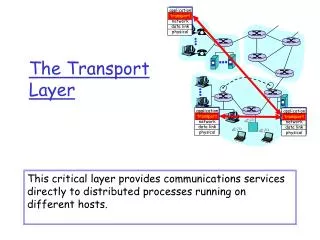
The Transport Layer • The transport layer is the heart of the whole protocol hierarchy. • Its task is to provide reliable, cost-effective data transport from the source machine to the destination machine, independently of the physical network or networks currently in use.
The Transport Service • Services Provided to the Upper Layers • Transport Service Primitives • Berkeley Sockets • An Example of Socket Programming: • An Internet File Server
Services Provided to the Upper Layers • The hardware and/or software within the transport layer that does the work is called the transport entity. • The transport entity can be located in the operating system kernel, in a separate user process, in a library package bound into network applications, or conceivably on the network interface card. • The transport layer service is so similar to the network layer service, then why 2 layers? • The transport code runs entirely on the users' machines, but the network layer mostly runs on the routers, which are operated by the carrier. • The users have no real control over the network layer. • The only possibility is to put on top of the network layer another layer that improves the quality of the service.
Services Provided to the Upper Layers • Thanks to the transport layer, application programmers can write code without having to worry about dealing with different subnet interfaces and unreliable transmission. • The bottom four layers can be seen as the transport service provider, whereas the upper layer(s) are the transport service user. • Transport layer forms the major boundary between the provider and user.
Services Provided to the Upper Layers The network, transport, and application layers. TPDU (Transport Protocol Data Unit)
Transport Service Primitives • Each transport service has its own interface. • The transport service is similar to the network service, but real networks can lose packets, so the network service is generally unreliable. • The purpose of the transport layer—to provide a reliable service on top of an unreliable network. • The connection oriented transport service is all about—hiding the imperfections of the network service so that user processes can just assume the existence of an error-free bit stream.
Transport Service Primitives The primitives for a simple transport service.
Transport Service Primitives • TPDU (Transport Protocol Data Unit) for messages sent from transport entity to transport entity. • TPDUs (exchanged by the transport layer) are contained in packets (exchanged by the network layer). • Packets are contained in frames (exchanged by the data link layer). • When a frame arrives, the data link layer processes the frame header and passes the contents of the frame payload field up to the network entity. • The network entity processes the packet header and passes the contents of the packet payload up to the transport entity.(Next slide)
Transport Service Primitives (2) The nesting of TPDUs, packets, and frames.
Transport Service Primitives • At the transport layer, even a simple unidirectional data exchange is more complicated than at the network layer. • Every data packet sent will be acknowledged. • These acknowledgements are managed by the transport entities, using the network layer protocol, and are not visible to the transport users. • To the transport users, a connection is a reliable bit pipe: one user stuffs bits in and they magically appear at the other end. • Disconnection has two variants: asymmetric and symmetric. • In the asymmetric variant, either transport user can issue a DISCONNECT primitive. • In the symmetric variant, each direction is closed separately, independently of the other one.
Transport Service Primitives (3) A state diagram for a simple connection management scheme. Transitions labeled in italics are caused by packet arrivals. The solid lines show the client's state sequence. The dashed lines show the server's state sequence.
Berkeley Sockets The socket primitives used in Berkeley UNIX for TCP. (Connection release with sockets is symmetric, both have to close) The socket primitives for TCP.
Elements of Transport Protocols • Addressing • Connection Establishment • Connection Release • Flow Control and Buffering • Multiplexing • Crash Recovery
Elements of Transport Protocols • The transport service is implemented by a transport protocol used between the two transportentities. • Deals with error control, sequencing, and flow control, etc.. Differences between Data Link Layer and Transport Layer (next slide) • In DLL, explicit addressing of destinations is not required, in the transport layer, explicit addressing of destinations is required. • In DLL, the process of establishing a connection over the wire is simple, in the transport layer, initial connection establishment is more complicated. • In DLL no storage capacity, but exists in the subnet. • Amounts of buffering and flow control needed in both layers.
Transport Protocol (a) Environment of the data link layer. (b) Environment of the transport layer.
Addressing • The method normally used is to define transport addresses to which processes can listen for connection requests. • These end points are called ports. • We will use the generic term TSAP, (Transport Service Access Point). • Network layer addresses are called NSAPs. IP addresses areexamples of NSAPs. A scenario for a transport connection is as follows: 1. A ‘time of day’ server process on host 2 attaches itself to TSAP 1522 to wait for an incoming call. 2. An application process on host 1 wants to find out the time-of-day, so it issues a CONNECT request specifying TSAP 1208 as the source and TSAP 1522 as the destination.
Addressing TSAPs, NSAPs and transport connections.
Addressing 3. The application process then sends over a request for the time. 4. The ‘time server’ process responds with the current time. 5. The transport connection is then released. • stable TSAP addresses that are listed in files gives which servers are permanently attached to which ports. • If there are potentially many server processes, most of which are rarely used, it is wasteful to have each of them active and listening to a stable TSAP address all day long. A better scheme • It is known as the initial connection protocol. • A special process server that acts as a proxy for less heavily used servers.
Connection Establishment How a user process in host 1 establishes a connection with a time-of-day server in host 2.
Addressing • It listens to a set of ports at the same time, waiting for a connection request. • Potential users of a service begin by doing a CONNECT request, specifying the TSAP address of the service they want. • If no server is waiting for them, they get a connection to the process server. • After it gets the incoming request, the process server spawns the requested server, allowing it to inherit the existing connection with the user. • The new server then does the requested work, while the process server goes back to listening for new requests.
Addressing • A file server, for example, needs to run on special hardware (a machine with a disk) and cannot just be created on-the-fly when someone wants to talk to it. • An alternative scheme, a special process called a name server or sometimes a directory server is used. • A user sets up a connection to the name server (which listens to a well-known TSAP). • The user then sends a message specifying the service name, and the name server sends back the TSAP address. • Then the user releases the connection with the name server and establishes a new one with the desired service. • When a new service is created, it must register itself with the name server, giving both its service name (ASCII string) and its TSAP. • Name server provides a mapping of names onto numbers.
Connection Establishment • Establishing a connection is actually surprisingly tricky. • The problem occurs when the network can lose, store, and duplicate packets. This behavior causes serious complications. The worst possible nightmare is as follows: • User establishes a connection with bank, requests huge amount transaction. • Unfortunately, each packet in the scenario is duplicated and stored in the subnet. • After the connection has been released, all the packets pop out of the subnet and arrive at the destination in order. • The bank has no way of telling that these are duplicates, and transfers the money again.
Connection Establishment • The crux of the problem is the existence of delayed duplicates. • One solution is to use throw-away transport addresses. • In this approach, each time a transport address is needed, a new one is generated. • When a connection is released, the address is discarded and never used again. • Another solution is to give each connection a connection identifier. • After each connection is released, each transport entity could update a table listing obsolete connections as (peer transport entity, connection identifier) pairs. • But, it requires each transport entity to maintain a certain amount of history information indefinitely.
Connection Establishment • If we can ensure that no packet lives longer than some known time, the problem becomes somewhat more manageable. • Packet lifetime can be restricted to a known maximum using one (or more) of the following techniques: • Restricted subnet design. • Prevents packets from looping. 2. Putting a hop counter in each packet. 3. Timestamping each packet. • Requires the router clocks to be synchronized, which itself is a nontrivial task.
Connection Establishment (3) Three protocol scenarios for establishing a connection using a three-way handshake. CR denotes CONNECTION REQUEST. (a) Normal operation, (b) Old CONNECTION REQUEST appearing out of nowhere. (c) Duplicate CONNECTION REQUEST and duplicate ACK.
Connection Release • Releasing a connection is easier than establishing one. • There are two styles of terminating a connection: asymmetric release and symmetric release. • Asymmetric release is the way the telephone system works: when one party hangs up, the connection is broken. • Symmetric release treats the connection as two separate unidirectional connections and requires each one to be released separately. • Asymmetric release is abrupt and may result in data loss. • Symmetric: One can envision a protocol in which host 1 says: I am done. Are you done too? If host 2 responds: I am done too. Goodbye, the connection can be safely released. • This protocol does not always work. This problem is called the two-army problem.
Connection Release Abrupt disconnection with loss of data.
Connection Release Two-army problem: • White army in valley, Blue army1 and Blue army2 on either side of hills. • White army is bigger than either of them, but both blue together are bigger than white army. • Blue can win only if they attack together. • Only communication is through the valley(uncertain), they can not attack together unless acknowledge comes from the other side.
Connection Release (2) The two-army problem.
Connection Release (3) 6-14, a, b DR(DISCONNECTION REQUEST) Four protocol scenarios for releasing a connection. (a) Normal case of a three-way handshake. (b) final ACK lost.
Connection Release (4) 6-14, c,d (c) Response lost. (d) Response lost and subsequent DRs lost.
Connection Release • It can fail if the initial DR and N retransmissions are all lost. • The sender will give up and release the connection, while the other side knows nothing at all about the attempts to disconnect and is still fully active. • This situation results in a half-open connection. • One way to kill off half-open connections is to have a rule saying that if no TPDUs have arrived for a certain number of seconds, the connection is then automatically disconnected.
Flow Control and Buffering • DL and TP layers use sliding window or other scheme on each connection to keep a fast transmitter from overrunning a slow receiver. • If the network service is unreliable, the sender must buffer all TPDUs sent. • If the sender knows that the receiver always has buffer space, it need not retain copies of the TPDUs it sends. • If the receiver cannot guarantee that every incoming TPDU will be accepted, the sender will have to buffer anyway. • Variable size buffer: The advantage is better memory utilization, at the price of more complicated buffer management.(next slide) • Large Circular buffer: Makes good use of memory, provided that all connections are heavily loaded, but is poor if some connections are lightly loaded.
Flow Control and Buffering (a) Chained fixed-size buffers. (b) Chained variable-sized buffers. (c) One large circular buffer per connection.
Flow Control and Buffering • For low-bandwidth bursty traffic, it is better to buffer at the sender. • For high bandwidth smooth traffic, it is better to buffer at the receiver. • As connections are opened and closed and as the traffic pattern changes, the sender and receiver need to dynamically adjust their buffer allocations. • The transport protocol should allow a sending host to request buffer space at the other end. • Buffers could be allocated per connection, or collectively, for all the connections running between the two hosts. • The receiver, knowing its buffer situation (but not knowing the offered traffic) could tell the sender ''I have reserved X buffers for you.'‘
Flow Control and Buffering (2) Dynamic buffer allocation. The arrows show the direction of transmission. An ellipsis (…) indicates a lost TPDU.
Flow Control and Buffering • To prevent deadlock situation, each host should periodically send control TPDUs giving the acknowledgement and buffer status on each connection. • As memory prices continue to fall dramatically, lack of buffers is not a problem. • Another bottleneck is the carrying capacity of the subnet. • If the network can handle c TPDUs/sec and the cycle time (including transmission, propagation, queueing, processing at the receiver, and return of the acknowledgement) is r, then the sender's window should be cr. • In order to adjust the window size periodically, the sender could monitor both parameters and then compute the desired window size.
Multiplexing • If only one network address is available on a host, all transport connections on that machine have to use it. • When a TPDU comes in, some way is needed to tell which process to give it to. This situation, called upward Multiplexing. • A subnet uses virtual circuits internally and imposes a maximum data rate on each one. • If a user needs more bandwidth than one virtual circuit can provide, a way out is to open multiple network connections and distribute the traffic among them on a round-robin basis, this is called downward multiplexing.
Multiplexing (a) Upward multiplexing. (b) Downward multiplexing.
Crash Recovery • If the transport entity is entirely within the hosts, recovery from network and router crashes is straightforward. • A more troublesome problem is how to recover from host crashes. • Partway through the transmission of a big file, the server crashes. When it comes back up, its tables are reinitialized, so it no longer knows precisely where it was. • The server might send a broadcast TPDU to all other hosts, announcing that it had just crashed and requesting that its clients inform it of the status of all open connections. • Each client can be in one of two states: one TPDU outstanding, S1, or no TPDUs outstanding, S0.
Crash Recovery • No matter how the client and server are programmed, there are always situations where the protocol fails to recover properly. • The server can be programmed in one of two ways: acknowledge first or write first. • The client can be programmed in one of four ways: always retransmit the last TPDU, never retransmit the last TPDU, retransmit only in state S0, or retransmit only in state S1. • This gives eight combinations, but as we shall see, for each combination there is some set of events that makes the protocol fail. • Three events are possible at the server: sending an acknowledgement (A), writing to the output process (W), and crashing (C).
Crash Recovery • The three events can occur in six different orderings: AC(W), AWC, C(AW), C(WA), WAC, and WC(A) • Where the parentheses are used to indicate that neither A nor W can follow C. • The conclusion is inescapable: under our ground rules of no simultaneous events, host crash and recovery cannot be made transparent to higher layers.
Crash Recovery Different combinations of client and server strategy.
A Simple Transport Protocol • The Example Service Primitives • The Example Transport Entity • The Example as a Finite State Machine
The Example Service Primitives • Have a library procedure connect. • The parameters are the local and remote TSAPs. • When a process wants to be able to accept incoming calls, it calls listen, specifying a particular TSAP to listen to. • Hold the connection request at the receiving end for a certain time interval. If a process on that host calls listen before the timer goes off, theconnection is established; otherwise, it is rejected and the caller is unblocked and given an error return. • This model is highly asymmetric. One side is passive, executing a listen and waiting until something happens. The other side is active and initiates the connection. • To release a connection, we will use a procedure disconnect. • When both sides have disconnected, the connection is released.(symmetric)
The Example Service Primitives • Data transmission: sending is active but receiving is passive. • Concrete service definition therefore consists of five primitives: CONNECT, LISTEN, DISCONNECT, SEND, and RECEIVE. • Each primitive corresponds exactly to a library procedure that executes the primitive.
The Example Transport Entity (2) • The transport entity has been programmed as though it were a library package. • The ''transport entity'' is not really a separate entity at all, but part of the user process. Each connection is in one of seven states: • Idle – Connection not established yet. • Waiting – CONNECT has been executed, CALL REQUEST sent. • Queued – A CALL REQUEST has arrived; no LISTEN yet. • Established – The connection has been established. • Sending – The user is waiting for permission to send a packet. • Receiving – A RECEIVE has been done. • DISCONNECTING – a DISCONNECT has been done locally.
The Example as a Finite State Machine (2) The example protocol in graphical form. Transitions that leave the connection state unchanged have been omitted for simplicity.
The Internet Transport Protocols: UDP • The connectionless protocol is UDP. • The connection-oriented protocol is TCP. • Introduction to UDP • Remote Procedure Call • The Real-Time Transport Protocol