Download
1 / 36
360 likes | 568 Views
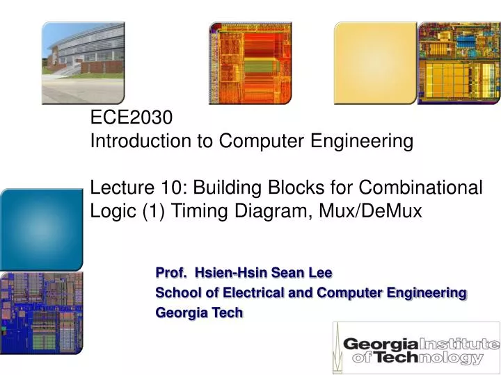
ECE2030 Introduction to Computer Engineering Lecture 10: Building Blocks for Combinational Logic (1) Timing Diagram, Mux/DeMux. Prof. Hsien-Hsin Sean Lee School of Electrical and Computer Engineering Georgia Tech. N inputs. M outputs. Combinational circuits. Combinational Logic.

E N D
ECE2030 Introduction to Computer EngineeringLecture 10: Building Blocks for Combinational Logic (1) Timing Diagram, Mux/DeMux Prof. Hsien-Hsin Sean Lee School of Electrical and Computer Engineering Georgia Tech
N inputs M outputs Combinational circuits Combinational Logic • Outputs, “at any time”, are determined by the input combination • When input changed, output changed immediately • Real circuits is imperfect and have “propagation delay” • A combinational circuit • Performs logic operations that can be specified by a set of Boolean expressions • Can be built hierarchically
Timing Diagram • Describe the functionality of a logic circuit across time • Represented by a waveform • For combinational logic, Output is a function of inputs
A B Timing Diagram of an AND Gate (Output=AB) Time t0 t1 t2 t3 t4 t5 t6 t7 t8 t9 t10 t11 t12 Output (No Delay) Note that the Output change can occur “at any Time” for Combinational logic
t0 t1 t2 t3 t4 t5 t6 t7 t8 t9 t10 Timing Diagram Example Y A F X B Z A B X Y Z F
t0 t1 t2 t3 t4 t5 t6 t7 t8 t9 t10 F = A B F Timing Diagram Example Y A F X B Z A B
N inputs M outputs Combinational circuits Combinational Logic • Outputs, “at any time”, are determined by the input combination • We will discuss • Multiplexers / De-Multiplexers • Decoders / Encoders • Comparators • Parity Checkers / Generators • Binary Adders / Subtractors • Integer Multipliers
En A0 A1 F 4-to-1 Mux A2 A3 S1 S0 Multiplexers (Mux) • Functionality: Selection of a particular input • Route 1 of N inputs (A) to the output F • Require selection bits (S) • En(able) bit can disable the route and set F to 0
Multiplexers (Mux) w/out Enable A0 A1 F 4-to-1 Mux A2 A3 S1 S0
Multiplexers (Mux) w/out Enable A0 A1 F 4-to-1 Mux A2 A3 S1 S0
Logic Diagram of a 4-to-1 Mux S1 S0 F A0 A1 A2 A3
En A0 A1 F 4-to-1 Mux A2 A3 S1 S0 Multiplexers (Mux) w/ Enable
En 4-to-1 Mux w/ Enable Logic S1 S0 F A0 A1 A2 A3
En 4-to-1 Mux w/ Enable Logic S1 S0 F A0 A1 Reduce one Gate Delay by using 4-input AND gate for the 2nd level A2 A3 En
4-to-1 Mux using Transmission Gates S1 S0 A0 A1 F A2 A3
4-to-1 Mux using Transmission Gates S1 S0=0 A0 A0 A1 F A2 A2 A3
4-to-1 Mux using Transmission Gates S1=0 S0=0 A0 A0 A0 A1 F A2 A2 A2 A3
4-to-1 Mux using Transmission Gates S1 S0=1 A0 A0 A1 F A2 A2 A3
4-to-1 Mux using Transmission Gates S1=1 S0=1 A0 A0 A1 A1 F A2 A2 A3 A3
En S1=1 S0=1 A0 A0 A1 A2 A2 F A3 4-to-1 Mux using Transmission Gates with Enable (F=0 when En=0)
En=1 X=S0 Y=S0 X=En· S0 Y=En + En·S0 = En + S0 4-to-1 Mux using Transmission Gates with Enable (F=Z when En=0) A0 X Y A1 En=0 X=0 Y=1 (To disable both TG)
X=En· S0 Y=En + En·S0 = En + S0 4-to-1 Mux using Transmission Gates with Enable (F=Z when En=0) S0 A0 En X X Y Y A1
X=En· S0 Y=En + En·S0 = En + S0 4-to-1 Mux using Transmission Gates with Enable (F=Z when En=0) S0 A0 En A1 A2 A3
S1 4-to-1 Mux using Transmission Gates with Enable (F=Z when En=0) S0 A0 En F A1 A2 A3
X=En· S0 Y=En + En·S0 = En + S0 Simplified 4-to-1 Mux using TGs with Enable (F=Z when En=0) En S1 S0 A0 A0 X F Y A1 A2 A2 Only Disable the 2nd level A3
Quadruple 2-to-1 Line Mux En A[3:0] A3..0 2-to-1 Mux (4-bit bus) F[3:0] B3..0 B[3:0] SEL
A3 A2 A1 F3 F2 F1 B3 B2 B1 Quadruple 2-to-1 Line Mux A0 F0 Fx=Ax·En·SEL+Bx·En·SEL SEL B0 En
A0 A1 A2 8-to-1 Mux F A3 A4 A5 A6 A7 S2 S1 S0 B C A Design Canonical Form w/ MUX Each input in a MUX is a minterm 0 1 1 0 0 0 1 1
C Vdd Design Canonical Form w/ MUX En C A0 A1 F 4-to-1 Mux 0 A2 1 A3 S1 S0 B A
A Vdd Design Canonical Form w/ MUX En A0 A1 F 4-to-1 Mux A2 A A3 S1 S0 C B
A0 A1 F 4-to-1 Mux A2 A3 S1 S0 Demultiplexers (DeMux) D0 D1 1-to-4 DeMux A D2 D3 S1 S0
DeMux Operations D0 D1 1-to-4 DeMux A D2 D3 S1 S0
S1 D0 S0 D1 D2 D3 A DeMux Operations
S1 D0 S0 D1 D2 D3 En A DeMux Operations w/ Enable