Download
1 / 56
560 likes | 724 Views
UAE University College of Engineering Graduation Project II. Speech Controlled Automated Systems. Group Members: Hilmi Shawki Bahamid 199901453 Mohammed Eid 980211470 Abu Baker Yousif Khidir 980215254 Nader Ismail Al Zoubi 980215189 Advisor: Dr. Mousa Hussein 10 th June 2004.

E N D
UAE University College of Engineering Graduation Project II Speech Controlled Automated Systems Group Members: Hilmi Shawki Bahamid 199901453 Mohammed Eid 980211470 Abu Baker Yousif Khidir 980215254 Nader Ismail Al Zoubi 980215189 Advisor: Dr. Mousa Hussein 10th June 2004
Overview • Introduction • System Description • Participation at ENGEX 2004 • Voice Decoder Module • Microcontroller Module • Wireless Module • Robot Design and Control • Hardware Implementation • Conclusion and Recommendation
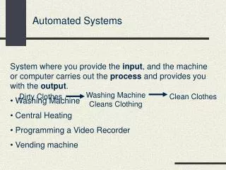
Goals: Control any electrical equipment in house by voice commands Control an autonomous vehicle by voice Benefits: Interactive life between humans and electrical devices Helping handicapped to control electrical devices at home by themselves (using their voice) Controlling high power electrical devices safely (children) Saving time and money Introduction Introduction
Voice Decoder Microcontroller Bluetooth Electrical System Power Switches Microcontroller Bluetooth System Description
How the system should work? System Description System Description Bluetooth Module Bluetooth Module Microcontroller Microcontroller Robot Voice Decoder Power Switch Sub-system Central Control Unit Lamp
Participation at ENGEX 2004 Participation at ENGEX 2004 • The ‘wired’ solution of this project was presented at ENGEX 2004. • System was able to switch ON and OFF house hold electrical devices • two lights • a fan • a fruit mixer • The project was presented in front of His Highness Sheikh Nahyan Bin Mubarak Al Nahyan.
Voice Decoder A. Introduction: • Decoder: A decoder is an electrical circuit that can (translate) a physical quantity into a digital electrical signal. • Why do we want a voice decoder in this project? • transform an analog signals into digital signals. 2. Decoder signal will be fed to an electrical brain. 3. the brain will make a decision on controlling the machine depending on the decoder digital signals.
Voice Decoder B. Speech recognition: Dependent vs. Independent • Speaker Dependent Recognition: Each of the words (to be recognized) should be spoken several times. 2. The product then recognizes these pre-trained words. 3. Training is a quick and simple process. • Speaker Independent Recognition: The decoder is pretrained for different speakers voices 2. No additional training by the user.
Voice Decoder B. Speech recognition: Dependent vs. Independent The differences between independent and dependent recognition
Voice Decoder C. Selecting Sensory Voice Direct TM II decoder: • Edge-Triggered, Continuous Listening and Word- Spotting speech recognition modes. • Recognizes up to 15 words or phrases. • Over 99% recognition accuracy with proper design. • Phrase recognition up to 2.5 seconds. • User-friendly speech prompting • Quick setup time.
Voice Decoder D. Preparing VDII to be integrated to other parts 1. MCL (Multi triggers Continuous Listening) mode was selected. 2. Relaxed Training (easier to train and accepts more similar sounding words). 3. Faster MCL (recognize triggering words quickly). • 4. low microphone sensitivity was selected (arm length). 5. A 20 line cable was used with VDII to make an efficient connection between the VDII and the microcontroller.
PWM Generation PWM signal generated from PIC 16f877
PWM Generation A. Introduction: • Very essential in controlling the switching frequency for the H-bridge (DC driver). • PWM signal in general: is a square wave with a variable duty cycle. • Controlling the duty cycle is to control the voltage applied to the motor. • PIC 16f877 Motorola was used to generate the PWM controlling signal. (it has two Capture/Compare/PWM modules)
PWM Generation Switching signal D.C controls the output voltage level from the DC driver H-bridge under a certain application’s frequency.
PWM Generation B. Using CCP module in PWM mode : • Capture/Compare/PWM Register1 (CCPR1) is comprised of two 8-bit registers.( CCPR1L and CCPR1H) • The CCP1CON register controls the operation of CCP1. • The special event trigger is generated by a compare match and will reset Timer1. CCP module versus the used timer
PWM Generation B. PWM signal period: PWM period = [(PR2) + 1] x 4 x TOSC x (TMR2 prescale value) • PR2 = Timer2 period register, TMR2 perscale value = value controls the used oscillator frequency by the module and TOSC = period of the used oscillator. C. PWM duty cycle: Duty Cycle = (CCPR1L:CCP1CON<5:4>) • TOSC • (TMR2 prescale value D. PWM resolution:
PWM Generation E. Setup for CCP operates in PWM mode : 1. Set the PWM period by writing to the PR2 register. 2. Set the PWM duty cycle by writing to the CCPR1L register and CCP1CON<5:4> bits. 3. Make the CCP1 pin an output by clearing the TRISC<2> bit. 4. Set the TMR2 prescale value and enable Timer2 by writing to T2CON. 5. Configure the CCP1 module for PWM operation.
Microcontroller Module Microcontroller Module • What is a microcontroller? • It is a cheap single chip microcomputer. • It is able to storing and running a program that was written, complied and downloaded into it. • Its main parts: • Central Processing Unit (CPU) • Random Access Memory (RAM) • Read Only Memory (ROM) • Input/output lines (I/O lines) • Serial and parallel ports, timers and other peripherals. • Why using a Microcontroller? • Microcontrollers are inexpensive microcomputers. • Function: input signals, translate it, then output the results.
Microcontroller Module Serial Communication (PIC16F877) • Serial I/O modules: • Universal Synchronous Asynchronous Receiver Transmitter (USART) (This was used). • Synchronous Serial Port (SSP). • USART configuration: • Full duplex asynchronous system (communicate with PC, another microcontroller). • Half duplex synchronous system (communicate with A/D or D/A IC).
Microcontroller Module Serial Communication (PIC16F877) (Cont.) • Pseudo code of the serial communication part: • Transmitter Microcontroller: • Initialize serial communications module • Move the required data to transmit into the working register (W) • Call the transmitting function • Move the data in (W) into register TXREG, which is responsible for transmitting the data serially.
Microcontroller Module Serial Communication (PIC16F877) (Cont.) • Pseudo code of the serial communication part: • Receiver Microcontroller: • Full Initialize serial communications module • Set interrupt handler • When data is received, interrupt occurs • Program goes into the interrupt handler, and move the data received to the working register (W) • Move the data in (W) to another temporary register.
Microcontroller Module Baud Rate Generator (BRG) • BRG is a dedicated 8-bit baud rate generator. • SPBRG register controls the period of a free running 8-bit timer. • High Baud Rate Select Bit (BRGH) is used in asynchronous mode.
Microcontroller Module Baud Rate Generator (BRG) • Example: FOSC = 4 MHz, Desired Baud Rate = 9600 bps, BRGH = 1, SYNC = 0 (Asynchronous mode) This error is quite small and can be ignored.
Microcontroller Module Problems Faced and Applied Solutions (Cont.) • Problem 1: The transmitter microcontroller is working fine, but the receiver is not responding. • Applied Solution to Problem 1: • Troubleshooting the hardware part (connections, test-board, and the oscilloscope) were working fine. • Troubleshooting the software part of the project (transmitter side code was working correctly). • Troubleshooting the receiving side code. It had some problems (They were solved). • Programming with assembly language is not an easy task.
Microcontroller Module Problems Faced and Applied Solutions (Cont.) • Problem 2 and its solution: Start up baud rate of the Bluetooth module was 115kbps. • Baud rate error will be high. • Example: FOSC = 4 MHz, Desired Baud Rate = 115200 bps, BRGH = 1, Asynchronous mode • 4MHz oscillator was replaced by 20MHz oscillator.
Why Wireless is needed? To connect between the microphone and the voice decoder. To connect the central unit to other sub-units (robot, room control system). Central Unit to Sub-units Connection: IR (line-of-site problem) is rejected. Home RF (Problems: high power consumption, high cost, high interference and no group management capabilities). Bluetooth (low cost, low power, group management capabilities). Microphone to Voice Decoder connection: Home RF was chosen; cheapness of wireless mikes. Wireless Communication Wireless Communication
Selection of the Bluetooth Module (ICM200); Why? The coverage range of the ICM200 is greater than the ROK101800 (300m compared to 100m). ICM200 has regular pin connectors, which makes the module much easier to be mounted on a PCB (the ROK is a surface mounted module). Protocol Implementation: Only HCI layer was implemented. 21 HCI commands were implemented in assembly language. Wireless Communication Bluetooth
Wireless Communication HCI Commands HCI_Reset Command Implementation • HCI commands are sent to the module through the serial port interface.
Connection Procedures: Send the HCI_Reset command to reset the module. Send the HCI_Event_filter command to auto-accept connections. Send the HCI_Create_Connection command with the required Bluetooth device address. Sending Data: Construct an ACL data packet with the data to be sent. Send the ACL data packet to the module. Wireless Communication Sending Data over Bluetooth
Supported Interfaces: USB (high data rate, complex to implement). PCM (used for voice transmition). UART (easy to implement, selected for this project). Wireless Communication Bluetooth Interface Bluetooth Interface Connection
The module didn’t respond the way it supposed to. It looped back the Read_Buffer_Size command instead of sending the Command_Complete event. Wireless Communication Bluetooth Interface Read_Buffer_Size command at the Oscilloscope
All error sources were checked with no results. Email Figure Wireless Communication Bluetooth Interface
We believe the problem is in the module itself. In summary: The protocol is fully implemented and tested. The interface was built according to the specification, however, the module didn’t work. We believe, if the module is replaced by another working one, the system should work fine. Wireless Communication Bluetooth Interface
Robot Design and Control Robot Picture
Robot is considered as a prototype for the wheelchair. The main idea was to control two motors using the PIC. Robot Design and Control Robot Design
LMD18200 driver was chosen because it: Delivers up to 3A continuous output. Operates at supply voltages up to 55V. Shorted load protection and easy control. Robot Design and Control DC Motor Driver
Robot Design and Control LMD18200 Pin Configuration
Robot Design and Control Robot Motion Control
Robot Mechanical Design • Problem • The high cost of the real wheel chair • Solution • The robot was made of inexpensive components to apply the system to a prototype of a real wheel-chair • It consists of • Three wheels; two are large and fixed while the third one is small and free (small ball wheel) • Plastic sheet (8.5 x 25cm) is used as the base of the robot to carry the robot controlling circuits and the batteries. • Two DC motors are used to control the fixed wheels, one for each wheel.
Robot Mechanical Design • Problem • Using two moving wheels caused the robot not to move in straight direction. • Solution • Replacing the two moving wheels by a small frictionless ball wheel.
Printed Circuit Boards (PCBs) • Three circuits were designed and implemented on printed circuit boards • These circuits are • Central Processing Unit Circuit • Power circuit • Robot Controlling Circuit • These circuits were designed using Eagle software and implemented using the chemical processing of PCB.
Printed Circuit Boards (PCBs) • Central Processing Unit Circuit • Interface circuit between the microcontroller and the Bluetooth module and the microcontroller and the voice decoder • Consists of: • Components: Bluetooth module, Microcontroller and power supply (3.3V, 5V and 9V) • Connectors: RS232 (9pin), Bluetooth connector and 20 pin connector to Voice Decoder
Printed Circuit Boards (PCBs) • Power Circuit (load) • Interface circuit between the microcontroller and the Bluetooth module and the microcontroller and the electromechanical relays • Consists of • Components: Bluetooth module, Microcontroller, four power transistors and power supply (5V & 3.3V) • Connectors: RS232 (9pin), Bluetooth connector and four connectors to power sockets
Printed Circuit Boards (PCBs) • Problem • The relay needs 72mA, while the microcontroller output is 25mA • Solution • Darlington power transistor (TIP126) was used to supplies the relay DC coil current