Download
1 / 35
550 likes | 841 Views
Design, Care and Feeding of NMR Probes: A Tutorial. 2011 Experimental NMR Conference, Asilomar CA. sources of inspiration. Don Alderman Mark Conradi David Hoult Bob McKay Eichii Fukuskima David Doty Toby Zens Frank Engelke Allen Palmer John Stringer . . . .

E N D
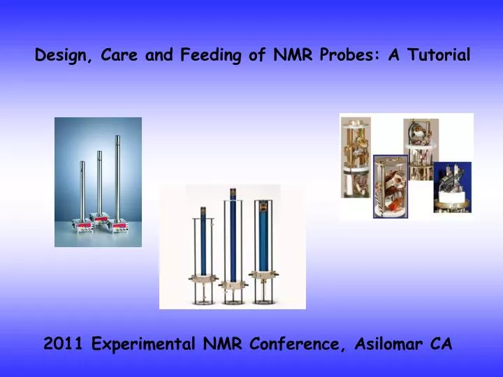
Design, Care and Feeding of NMR Probes: A Tutorial 2011 Experimental NMR Conference, Asilomar CA
sources of inspiration.... Don Alderman Mark Conradi David Hoult Bob McKay Eichii Fukuskima David Doty Toby Zens Frank Engelke Allen Palmer John Stringer . . . . and many, many, many others too numerous to mention .... David Hoult Mark Conradi Don Alderman David Doty Eichii Fukushima Bob McKay Toby Zens
Design, Care and Feeding of NMR Probes: A Tutorial Part I What is a tank circuit? Impedance matching transmission lines the Smith chart experimental techniques Circuit resonance Q and voltage rise arcing and avoiding arcing Part II Signal to noise Rf efficiency comparing specifications Circuit balancing and multiple resonance circuits Finite element field simulations Tuning tube and transmission line probes
Disclaimer: semi-professional driver on a closed track. Do not attempt at home. The "management" of ENC is not responsible for damages as a result. Opinions of the speaker do not reflect those of the ENC unless you happen to like them, and in that instance ENC takes full credit.. "it is easier to repent than it is to get permission" - D. M. Grant
signal emf = - NMR probe basics resonator An NMR probe is a tank circuit used to excite NMR signals and detect them by Faraday induction RF input impedance matching network
Bo N S B1(t) Resonators...type usually dictated by sample geometry and frequency Solenoidal coil Saddle coil all resonators are inductive elements slotted tube scroll coil Zens resonator bird cage
primitive probe transmission line RF input resonator very inefficient because of impedance mismatch RF signals have wave character and require phase matching
n1 n2 Impedance matching of light waves index of refraction n1 for p-polarized light the transmission coefficient depends on n1, n2 and the incident angle θ. index of refraction n2 R = 0 and T = 1 when
DC electronics basics – Ohm's Law V R V C V L V = IR RF electronics – Ohm's law works using Impedance V(t) = Vocos(ωt + φ) or V(t) = Re(ej(ωt +φ))
RF electronics basics – Impedance and Reactance V R V C V L V = IZR V = IZC V = IZL from V(t) = ej(ωt +φ) ZR = R Define a complex impedance Z ZC = 1/jωC ZL = jωL Z = R + jX X = Reactance
Transmission lines and characteristic impedance Can't just connect a load to a source with a wire – it will radiate the power ρ = | Γ | • The voltage standing wave ratio is then equal to: Dipole antenna radiates power from transmitter into space To transmit RF to a load need a structure to contain the EM waves
for dielectric Transmission lines and characteristic impedance twin-line d b coaxial line length l characteristic impedance Zo is the equivalent of a refractive index Minimum attenuation cable: if εR = 1.0, Zo = 75Ω; εR = 2.0, Zo = 51Ω
VSWR = Vmax/Vmin = (1 + |ΓL|)/(1 − |ΓL|) reflection coefficient if ZS = Zo = 50 Ω ZL = 50 Ω ZL = 25 Ω Vinc Vinc Vref Vref VSWR = 1 VSWR = 2 Vinc Vinc Vrefout of phase 180o for short Vrefin phase for open VSWR = ∞ VSWR = ∞
Impedance matching the coil R set X = 0 to find allowed ω there will be 2 ! Then choose CT/CM to render R' = Zo resonant frequency ω ~
easier to use a Smith chart 50Ω Example: match a 200Ω load L 200Ω C load 200Ω VSWR = 0
Measuring 1 Spectrum analyzer + tracking generator DUT 0 frequency matched RF receiver RF output Forward wave directional coupler reflected wave 50Ω
Resonator inductance for solenoid length , diameter d, n turns dimensions in inches usually more practical to measure L
Resonant RLC circuits when ω2 = 1/LC the circuit is "resonant" RF energy at ω is stored alternately in C and L Circuit can be excited by an antenna or other source
Zo Zo Zo Using resonance to span a break in a transmission line circuit
Zo Zo Zo Using resonance to span a break in a circuit L C
Impedance matching the coil R set X = 0 to find allowed ω there will be 2 ! Then choose CT/CM to render R' = Zo resonant frequency ω ~
Measuring Spectrum analyzer + tracking generator DUT frequency RF receiver RF output Forward wave directional coupler reflected wave 50Ω
Voltage at circuit resonance when ω2 = 1/LC Zin = R and |XC| = |XL|I = Vin/Zin = Vin/R What is the voltage VH – Vin across C?
Coil quality factor Q =ωL/R = E stored/E dissipated per cycle = ω/3dB bandwidth typical Q ~ 100 or more Input pulse power Peak V across C ~ 10,000 V !!! Vptp
Non-magnetic fixed and variable capacitors 500V Vacuum variable 2.5 kV 20 kV Sapphire trimmer 10 kV RF transmitting ceramic chips 2.5 kV Teflon variable
Probe testing under power Directional coupler output forward reflected Power amplifier
Probe testing under power arcing Directional coupler output reflected forward Power amplifier
Arc testing • tune and match at low power • increase drive 1 dB at a time while watching reflected power • operate 2 dB lower than initial arc • avoid hard sustained arcing – carbonized capacitors do not heal • don't try and rematch to compensate for arcing
Dewar's frequently provide sources of arcing If the probe only arcs in the magnet suspect the dewar
signal emf = - = B1 from unit current Part II.......maybe for next year Optimizing RF efficiency and S/N "principle of reciprocity" Excitation and detection are equally efficient
Acknowledgements • For inspiration and graphics • Abragam • D. VanderHart • M. Conradi • T. and H. Barbara • T. Zens • D. Alderman • B. Mckay • Palmer • J. Stringer • F. Engelke • G. Facey • J. Daniels • E. Fukushima • D. Doty L. Page S. Brin S. Wolfram J. Wales J. Hornak R. Schurko For support NSF ExxonMobil Agilent Yale University all of my present and former students
Disclaimer: semi-professional driver on a closed track. Do not attempt at home. The "management" of ENC is not responsible for damages as a result. Opinions of the speaker do not reflect those of the ENC unless you happen to like them, and in that instance ENC takes full credit.. "your students only learn your worst habits" - C. P. Slichter