Download
1 / 32
330 likes | 464 Views
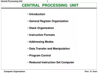
CENTRAL PROCESSING UNIT. Introduction General Register Organization Stack Organization Instruction Formats Addressing Modes Data Transfer and Manipulation Program Control Reduced Instruction Set Computer. MAJOR COMPONENTS OF CPU. Storage Components Registers

E N D
CENTRAL PROCESSING UNIT • Introduction • General Register Organization • Stack Organization • Instruction Formats • Addressing Modes • Data Transfer and Manipulation • Program Control • Reduced Instruction Set Computer
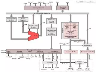
MAJOR COMPONENTS OF CPU • Storage Components • Registers • Flags • Execution (Processing) Components • Arithmetic Logic Unit(ALU) • Arithmetic calculations, Logical computations, Shifts/Rotates • Transfer Components • Bus • Control Components • Control Unit Register File ALU Control Unit
In Basic Computer, there is only one general purpose register, the Accumulator (AC) In modern CPUs, there are many general purpose registers It is advantageous to have many registers Transfer between registers within the processor are relatively fast Going “off the processor” to access memory is much slower REGISTERS
Input Clock R1 R2 R3 R4 R5 R6 R7 Load (7 lines) } { MUX MUX SELB SELA 3 x 8 A bus B bus decoder SELD ALU OPR Output GENERAL REGISTER ORGANIZATION
3 3 3 5 SELA SELB SELD OPR OPERATION OF CONTROL UNIT The control unit Directs the information flow through ALU by - Selecting various Components in the system - Selecting the Function of ALU Example: R1 R2 + R3 [1] MUX A selector (SELA): BUS A R2 [2] MUX B selector (SELB): BUS B R3 [3] ALU operation selector (OPR): ALU to ADD [4] Decoder destination selector (SELD): R1 Out Bus Control Word Encoding of register selection fields • Binary • CodeSELASELBSELD • 000 Input Input None • 001 R1 R1 R1 • 010 R2 R2 R2 • 011 R3 R3 R3 • 100 R4 R4 R4 • 101 R5 R5 R5 • 110 R6 R6 R6 • 111 R7 R7 R7
OPR Select Operation Symbol 00000 Transfer A TSFA 00001 Increment A INCA 00010 ADD A + B ADD 00101 Subtract A - B SUB 00110 Decrement A DECA 01000 AND A and B AND 01010 OR A and B OR 01100 XOR A and B XOR 01110 Complement A COMA 10000 Shift right A SHRA 11000 Shift left A SHLA ALU CONTROL Encoding of ALU operations
Symbolic Designation Microoperation SELA SELB SELD OPR Control Word • R1 R2 R3 R2 R3 R1 SUB 010 011 001 00101 • R4 R4 R5 R4 R5 R4 OR 100 101 100 01010 • R6 R6 + 1 R6 - R6 INCA 110 000 110 00001 • R7 R1 R1 - R7 TSFA 001 000 111 00000 • Output R2 R2 - None TSFA 010 000 000 00000 • Output Input Input - None TSFA 000 000 000 00000 • R4 shl R4 R4 - R4 SHLA 100 000 100 11000 • R5 0 R5 R5 R5 XOR 101 101 101 01100 ALU CONTROL Examples of ALU Microoperations
stack Address 63 Flags FULL EMPTY Stack pointer 4 SP C 3 6 bits B 2 A 1 0 DR REGISTER STACK ORGANIZATION Stack - Very useful feature for nested subroutines, nested interrupt services - Also efficient for arithmetic expression evaluation - Storage which can be accessed in LIFO - Pointer: SP - Only PUSH and POP operations are applicable Register Stack
REGISTER STACK ORGANIZATION Push, Pop operations /* Initially, SP = 0, EMPTY = 1, FULL = 0 */ PUSH POP • SP SP + 1 DR M[SP] • M[SP] DR SP SP 1 • If (SP = 0) then (FULL 1) If (SP = 0) then (EMPTY 1) • EMPTY 0 FULL 0
1000 Program PC (instructions) Data AR (operands) 3000 SP stack 3997 3998 3999 4000 4001 Stack grows In this direction MEMORY STACK ORGANIZATION Memory with Program, Data, and Stack Segments
MEMORY STACK ORGANIZATION • - A portion of memory is used as a stack with a • processor register as a stack pointer • - PUSH: SP SP - 1 • M[SP] DR • - POP: DR M[SP] • SP SP + 1 - Most computers do not provide hardware to check stack overflow (full stack) or underflow (empty stack) must be done in software
REVERSE POLISH NOTATION • Arithmetic Expressions: A + B A + B Infix notation + A B Prefix or Polish notation A B + Postfix or reverse Polish notation - The reverse Polish notation is very suitable for stack manipulation
Evaluation of Arithmetic Expressions Any arithmetic expression can be expressed in parenthesis-free Polish notation, including reverse Polish notation (3 * 4) + (5 * 6) 3 4 * 5 6 * + 6 4 5 5 30 12 12 42 3 3 12 12 3 * 5 * + 4 6 REVERSE POLISH NOTATION
In general, most processors are organized in one of 3 ways Single register (Accumulator) organization Basic Computer is a good example Accumulator is the only general purpose register General register organization Used by most modern computer processors Any of the registers can be used as the source or destination for computer operations Stack organization All operations are done using the hardware stack For example, an OR instruction will pop the two top elements from the stack, do a logical OR on them, and push the result on the stack PROCESSOR ORGANIZATION
INSTRUCTION FORMAT • Instruction Fields OP-code field - specifies the operation to be performed Address field - designates memory address(es) or a processor register(s) Mode field - determines how the address field is to be interpreted (to get effective address or the operand) • The number of address fields in the instruction format • depends on the internal organization of CPU • The three most common CPU organizations: • Single accumulator organization: • ADD X /* AC AC + M[X] */ • General register organization: • ADD R1, R2, R3 /* R1 R2 + R3 */ • ADD R1, R2 /* R1 R1 + R2 */ • MOV R1, R2 /* R1 R2 */ • ADD R1, X /* R1 R1 + M[X] */ • Stack organization: • PUSH X /* TOS M[X] */ • ADD
THREE, AND TWO-ADDRESS INSTRUCTIONS • Three-Address Instructions • Program to evaluate X = (A + B) * (C + D) : • ADD R1, A, B /* R1 M[A] + M[B] */ • ADD R2, C, D /* R2 M[C] + M[D] */ • MUL X, R1, R2 /* M[X] R1 * R2 */ • - Results in short programs • - Instruction becomes long (many bits) • Two-Address Instructions • Program to evaluate X = (A + B) * (C + D) : • MOV R1, A /* R1 M[A] */ • ADD R1, B /* R1 R1 + M[A] */ • MOV R2, C /* R2 M[C] */ • ADD R2, D /* R2 R2 + M[D] */ • MUL R1, R2 /* R1 R1 * R2 */ • MOV X, R1 /* M[X] R1 */
ONE, AND ZERO-ADDRESS INSTRUCTIONS • One-Address Instructions - Use an implied AC register for all data manipulation - Program to evaluate X = (A + B) * (C + D) : LOAD A /* AC M[A] */ ADD B /* AC AC + M[B] */ STORE T /* M[T] AC */ LOAD C /* AC M[C] */ ADD D /* AC AC + M[D] */ MUL T /* AC AC * M[T] */ STORE X /* M[X] AC */ • Zero-Address Instructions - Can be found in a stack-organized computer - Program to evaluate X = (A + B) * (C + D) : PUSH A /* TOS A */ PUSH B /* TOS B */ ADD /* TOS (A + B) */ PUSH C /* TOS C */ PUSH D /* TOS D */ ADD /* TOS (C + D) */ MUL /* TOS (C + D) * (A + B) */ POP X /* M[X] TOS */
ADDRESSING MODES • Addressing Modes • Specifies a rule for interpreting or modifying the address field of the • instruction (before the operand is actually referenced) • Variety of addressing modes • - to give programming flexibility to the user • - to use the bits in the address field of the • instruction efficiently
TYPES OF ADDRESSING MODES • Implied Mode • Address of the operands are specified implicitly in the definition of the instruction • - No need to specify address in the instruction • - EA = AC, or EA = Stack[SP] • - Examples from Basic Computer • CLA, CME, INP • Immediate Mode • Instead of specifying the address of the operand, operand itself is specified • - No need to specify address in the instruction • - However, operand itself needs to be specified • - Sometimes, require more bits than the address • - Fast to acquire an operand
TYPES OF ADDRESSING MODES • Register Mode • Address specified in the instruction is the register address • - Designated operand need to be in a register • - Shorter address than the memory address • - Saving address field in the instruction • - Faster to acquire an operand than the memory addressing • - EA = IR(R) (IR(R): Register field of IR) • Register Indirect Mode • Instruction specifies a register which contains • the memory address of the operand • - Saving instruction bits since register address • is shorter than the memory address • - Slower to acquire an operand than both the • register addressing or memory addressing • - EA = [IR(R)] ([x]: Content of x) • Autoincrement or Autodecrement Mode • - When the address in the register is used to access memory, the value in the register is incremented or decremented by 1 • automatically
TYPES OF ADDRESSING MODES • Direct Address Mode • Instruction specifies the memory address which can be used directly to access the memory • - Faster than the other memory addressing modes • - Too many bits are needed to specify the address for a large physical memory space • - EA = IR(addr) (IR(addr): address field of IR) • Indirect Addressing Mode • The address field of an instruction specifies the address of a memory location that contains the address of the operand • - When the abbreviated address is used large physical memory can be addressed with a relatively small number of bits • - Slow to acquire an operand because of an additional memory access • - EA = M[IR(address)]
TYPES OF ADDRESSING MODES • Relative Addressing Modes • The Address fields of an instruction specifies the part of the address (abbreviated address) which can be used along with a designated register to calculate the address of the operand • - Address field of the instruction is short • - Large physical memory can be accessed with a small number of address bits • - EA = f(IR(address), R), R is sometimes implied • 3 different Relative Addressing Modes depending on R; • *PC Relative Addressing Mode(R = PC) • - EA = PC + IR(address) • * Indexed Addressing Mode (R = IX, where IX: Index Register) • - EA = IX + IR(address) • * Base Register Addressing Mode • (R = BAR, where BAR: Base Address Register) • - EA = BAR + IR(address)
ADDRESSING MODESEXAMPLES Address Memory 200 Load to AC Mode Address = 500 PC = 200 201 202 Next instruction R1 = 400 399 450 XR = 100 400 700 AC 500 800 600 900 702 325 Addressing Mode Effective Address Content of AC • Direct address 500 /* AC (500) */ 800 • Immediate operand - /* AC 500 */ 500 • Indirect address 800 /* AC ((500)) */ 300 • Relative address 702 /* AC (PC+500) */ 325 • Indexed address 600 /* AC (XR+500) */ 900 • Register - /* AC R1 */ 400 • Register indirect 400 /* AC (R1) */ 700 • Autoincrement 400 /* AC (R1)+ */ 700 • Autodecrement 399 /* AC -(R) */ 450 800 300
ADDRESSING MODESEXAMPLES Address Memory Direct address 500 /* AC (500) */ 800 200 Load to AC Mode Address = 500 PC = 200 201 202 Next instruction R1 = 400 399 450 XR = 100 400 700 AC 500 800 600 900 702 325 Addressing Mode Effective Address Content of AC • Direct address 500 /* AC (500) */ 800 • Immediate operand - /* AC 500 */ 500 • Indirect address 800 /* AC ((500)) */ 300 • Relative address 702 /* AC (PC+500) */ 325 • Indexed address 600 /* AC (XR+500) */ 900 • Register - /* AC R1 */ 400 • Register indirect 400 /* AC (R1) */ 700 • Autoincrement 400 /* AC (R1)+ */ 700 • Autodecrement 399 /* AC -(R) */ 450 800 300
ADDRESSING MODESEXAMPLES Address Memory 200 Load to AC Mode Immediate operand - /* AC 500 */ 500 Address = 500 PC = 200 201 202 Next instruction R1 = 400 399 450 XR = 100 400 700 AC 500 800 600 900 702 325 Addressing Mode Effective Address Content of AC • Direct address 500 /* AC (500) */ 800 • Immediate operand - /* AC 500 */ 500 • Indirect address 800 /* AC ((500)) */ 300 • Relative address 702 /* AC (PC+500) */ 325 • Indexed address 600 /* AC (XR+500) */ 900 • Register - /* AC R1 */ 400 • Register indirect 400 /* AC (R1) */ 700 • Autoincrement 400 /* AC (R1)+ */ 700 • Autodecrement 399 /* AC -(R) */ 450 800 300
ADDRESSING MODESEXAMPLES Address Memory 200 Load to AC Mode Indirect address 800 /* AC ((500)) */ 300 Address = 500 PC = 200 201 202 Next instruction R1 = 400 399 450 XR = 100 400 700 AC 500 800 600 900 702 325 Addressing Mode Effective Address Content of AC • Direct address 500 /* AC (500) */ 800 • Immediate operand - /* AC 500 */ 500 • Indirect address 800 /* AC ((500)) */ 300 • Relative address 702 /* AC (PC+500) */ 325 • Indexed address 600 /* AC (XR+500) */ 900 • Register - /* AC R1 */ 400 • Register indirect 400 /* AC (R1) */ 700 • Autoincrement 400 /* AC (R1)+ */ 700 • Autodecrement 399 /* AC -(R) */ 450 800 300
ADDRESSING MODESEXAMPLES Address Memory 200 Load to AC Mode Relative address 702 /* AC (PC+500) */ 325 Address = 500 PC = 200 201 202 Next instruction R1 = 400 399 450 XR = 100 400 700 AC 500 800 600 900 702 325 Addressing Mode Effective Address Content of AC • Direct address 500 /* AC (500) */ 800 • Immediate operand - /* AC 500 */ 500 • Indirect address 800 /* AC ((500)) */ 300 • Relative address 702 /* AC (PC+500) */ 325 • Indexed address 600 /* AC (XR+500) */ 900 • Register - /* AC R1 */ 400 • Register indirect 400 /* AC (R1) */ 700 • Autoincrement 400 /* AC (R1)+ */ 700 • Autodecrement 399 /* AC -(R) */ 450 800 300
ADDRESSING MODESEXAMPLES Address Memory 200 Load to AC Mode Indexed address 600 /* AC (XR+500) */ 900 Address = 500 PC = 200 201 202 Next instruction R1 = 400 399 450 XR = 100 400 700 AC 500 800 600 900 702 325 Addressing Mode Effective Address Content of AC • Direct address 500 /* AC (500) */ 800 • Immediate operand - /* AC 500 */ 500 • Indirect address 800 /* AC ((500)) */ 300 • Relative address 702 /* AC (PC+500) */ 325 • Indexed address 600 /* AC (XR+500) */ 900 • Register - /* AC R1 */ 400 • Register indirect 400 /* AC (R1) */ 700 • Autoincrement 400 /* AC (R1)+ */ 700 • Autodecrement 399 /* AC -(R) */ 450 800 300
ADDRESSING MODESEXAMPLES Address Memory 200 Load to AC Mode Register - /* AC R1 */ 400 Address = 500 PC = 200 201 202 Next instruction R1 = 400 399 450 XR = 100 400 700 AC 500 800 600 900 702 325 Addressing Mode Effective Address Content of AC • Direct address 500 /* AC (500) */ 800 • Immediate operand - /* AC 500 */ 500 • Indirect address 800 /* AC ((500)) */ 300 • Relative address 702 /* AC (PC+500) */ 325 • Indexed address 600 /* AC (XR+500) */ 900 • Register - /* AC R1 */ 400 • Register indirect 400 /* AC (R1) */ 700 • Autoincrement 400 /* AC (R1)+ */ 700 • Autodecrement 399 /* AC -(R) */ 450 800 300
ADDRESSING MODESEXAMPLES Address Memory 200 Load to AC Mode Address = 500 PC = 200 201 202 Next instruction • Register indirect 400 • /* AC (R1) */ 700 R1 = 400 399 450 XR = 100 400 700 AC 500 800 600 900 702 325 Addressing Mode Effective Address Content of AC • Direct address 500 /* AC (500) */ 800 • Immediate operand - /* AC 500 */ 500 • Indirect address 800 /* AC ((500)) */ 300 • Relative address 702 /* AC (PC+500) */ 325 • Indexed address 600 /* AC (XR+500) */ 900 • Register - /* AC R1 */ 400 • Register indirect 400 /* AC (R1) */ 700 • Autoincrement 400 /* AC (R1)+ */ 700 • Autodecrement 399 /* AC -(R) */ 450 800 300
ADDRESSING MODESEXAMPLES Address Memory Autoincrement 400 /* AC (R1)+ */ 700 200 Load to AC Mode Address = 500 PC = 200 201 202 Next instruction R1 = 400 399 450 XR = 100 400 700 AC 500 800 600 900 702 325 Addressing Mode Effective Address Content of AC • Direct address 500 /* AC (500) */ 800 • Immediate operand - /* AC 500 */ 500 • Indirect address 800 /* AC ((500)) */ 300 • Relative address 702 /* AC (PC+500) */ 325 • Indexed address 600 /* AC (XR+500) */ 900 • Register - /* AC R1 */ 400 • Register indirect 400 /* AC (R1) */ 700 • Autoincrement 400 /* AC (R1)+ */ 700 • Autodecrement 399 /* AC -(R) */ 450 800 300
ADDRESSING MODESEXAMPLES Address Memory 200 Load to AC Mode Address = 500 PC = 200 201 • Autodecrement 399 • /* AC -(R) */ 450 202 Next instruction R1 = 400 399 450 XR = 100 400 700 AC 500 800 600 900 702 325 Addressing Mode Effective Address Content of AC • Direct address 500 /* AC (500) */ 800 • Immediate operand - /* AC 500 */ 500 • Indirect address 800 /* AC ((500)) */ 300 • Relative address 702 /* AC (PC+500) */ 325 • Indexed address 600 /* AC (XR+500) */ 900 • Register - /* AC R1 */ 400 • Register indirect 400 /* AC (R1) */ 700 • Autoincrement 400 /* AC (R1)+ */ 700 • Autodecrement 399 /* AC -(R) */ 450 800 300