Download
1 / 23
230 likes | 363 Views
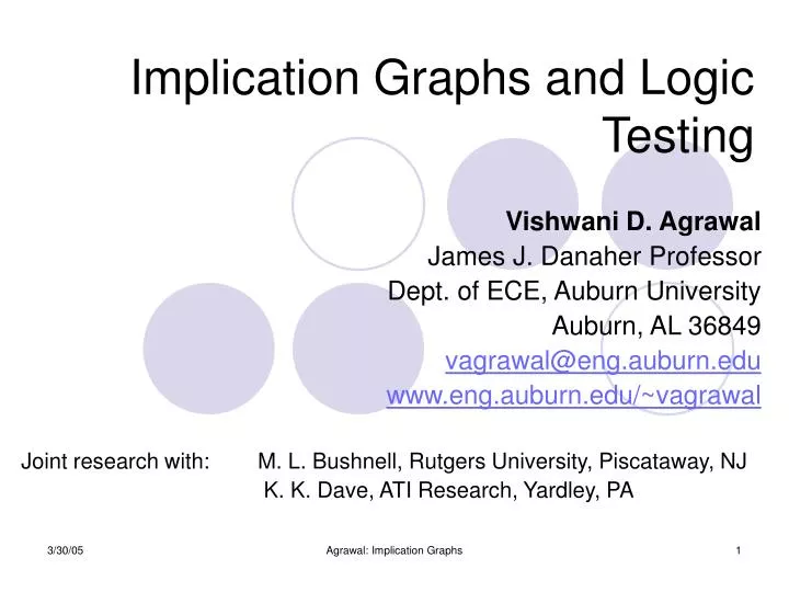
Implication Graphs and Logic Testing. Vishwani D. Agrawal James J. Danaher Professor Dept. of ECE, Auburn University Auburn, AL 36849 vagrawal@eng.auburn.edu www.eng.auburn.edu/~vagrawal Joint research with: M. L. Bushnell, Rutgers University, Piscataway, NJ

E N D
Implication Graphs and Logic Testing Vishwani D. Agrawal James J. Danaher Professor Dept. of ECE, Auburn University Auburn, AL 36849 vagrawal@eng.auburn.edu www.eng.auburn.edu/~vagrawal Joint research with: M. L. Bushnell, Rutgers University, Piscataway, NJ K. K. Dave, ATI Research, Yardley, PA Agrawal: Implication Graphs
Implication Graph • An implication graph (IG) represents the implication relations between pairs of Boolean variables. a b an implication contrapositive implication a b Agrawal: Implication Graphs
a c b Implication Graph of a Logic Gate c = ab Boolean false function:ab c = 0 ac + bc + abc = 0 a c b c a b • Chakradhar et al. -- IEEE-D&T, 1990 Agrawal: Implication Graphs
Global Implications and Transitive Closure a c b a c b Transitive closure edge c a b c ≡ 0 Agrawal: Implication Graphs
Transitive Closure • Transitive closure (TC) of a directed graph contains the same set of nodes as the original graph. • If there is a directed path from node a to b, then the transitive closure contains an edge from a to b. A Graph Transitive Closure a a b a b c d a 0 1 0 0 b 0 0 1 0 c 0 0 0 1 d 0 0 0 0 b a b c d a 0 1 11 b 0 0 1 1 c 0 0 0 1 d 0 0 0 0 d d c c A graph Agrawal: Implication Graphs
Transitive Closure: Warshall’s Algorithm procedureWarshall (varA : array[1…n, 1…n] of boolean; C : array[1…n, 1…n] of boolean); { Warshall makes A the transitive closure of C } var i, j, k : integer; begin fori := 1 tondo forj := 1 tondo A[i, j] := C[i, j]; fork := 1 tondo O(n3) fori := 1 tondo forj := 1 tondo if A[i, j] = false then A[i, j] := A[i, k] andA[k, j] end; { Warshall } S. Warshall, “A Theorem on Boolean Matrices,” J. ACM, vol. 9, no. 1, pp. 11-12, 1962. A. V. Aho, J. E. Hopcroft and J. D. Ullman, Data Structures and Algorithms, Reading, Massachusetts: Addison-Wesley, 1983, p. 213. Agrawal: Implication Graphs
Transitive Closure: Update Algorithm • Start constructing transitive closure (TC) by placing all nodes and no edges. This edge-less graph is its own TC. • Add edges to TC in any arbitrary order • For each edge i → j find • P : set of parent nodes of i • C : set of child nodes of j • Add edges {P, i } → {C, j } K. Dave, “Using Contrapositive Rule to Enhance the Implication Graphs of Logic Circuits,” Master’s Thesis, Rutgers University, Dept. of ECE, Piscataway, New Jersey, May 2004. Agrawal: Implication Graphs
Update Algorithm p2 p1 {P, i } Edges before i→ j is added i Edges after i→ j is added j {C, j } c1 Agrawal: Implication Graphs
a b c d Update Algorithm Example a b a b c d c d A directed graph a a a b b b c c c d d d Transitive closure Agrawal: Implication Graphs
Logic Testing: Stuck-at Fault • A type of fault, which causes a line to hold a constant logic value, irrespective of change of state at previous stages. • There are two types of stuck-at-faults: • Stuck-at-1 • Stuck-at-0 • Detection of a fault requires the fault to be activated and its effect observed at a primary output (PO). • Fault a s-a-1 is detectable, if following conditions are simultaneously satisfied: • a = 0 fault is activated • Oa = 1 “observability” is true Agrawal: Implication Graphs
OCb Oa = 0 OcOa + bOa + OcbOa = 0 Observability Variables Observability variable of a signal represents whether or not that signal is observable at a PO. It can be true or false. Oa Oc= 1 Oc a b Oa c b (PO) Ob Agrawal, Bushnell and Lin, “Redundancy Identification using Transitive Closure,” Proc.Asian Test Symp., 1996, pp. 5-9. Agrawal: Implication Graphs
Redundant Faults • A fault that has no test is called an untestable fault. • Any untestable fault in a combinational circuit is a redundant fault because it does not cause any change in the input/output logic function of the circuit. • Identification of redundant faults is useful because they can be removed • from testing consideration, or • from hardware • Fault a stuck-at-1 is redundant if • either a≡ 1 no controllability • or Oa ≡ 0 no observability • or a = 0 → Oa = 0no drivability • or Oa → a no drivability Agrawal: Implication Graphs
Od Oc Limitation of Implication Graph c a b c d a s-a-0 e s-a-0 b d Circuit with two redundant faults Implication graph (some nodes and edges not shown) Implication graph shows no implications of c and d on their observabilities. Agrawal: Implication Graphs
a c b Adding Partial Implications c = ab Boolean false function:ab c = 0 ac + bc + abc = 0 a c b Henftling and Wittmann, AEÜ, 1995 (Λ node) Λ Dave, Master’s Thesis, 2004 (V node) c a b Λ and V nodes represent partial implications V Agrawal: Implication Graphs
Od Oc Using Partial Implications c a b c d a s-a-0 e s-a-0 b d Circuit with two redundant faults Implication graph (some nodes and edges not shown) Implication Partial implication Transitive closure edge Agrawal: Implication Graphs
Another Example s-a-0 s-a-1 a c b s-a-0 e s-a-0 s-a-1 d Contrapositive of đ→ ē e a c d b Λ2 Λ1 Λ3 a e c d b e ≡ 0 Λ4 V1 V2 Agrawal: Implication Graphs
Results on ISCAS Circuits aSun SPARC5 CPU Sec. bSun SPARC2 CPU Sec. Agrawal: Implication Graphs
Referenced Methods • TRAN – ATPG • S. T. Chakradhar, V. D. Agrawal and S. G. Rothweiler, “A Transitive Closure Algorithm for Test Generation,” IEEE Trans. CAD, vol. 12, no. 7, pp. 1015-1028, July 1993. • FIRE – Implication analysis • M. A. Iyer and M. Abramovici, “FIRE: A Fault-Independent Combinational Redundancy Identification Algorithm,” IEEE Trans. VLSI Systems, vol. 4, no. 2, pp. 295-301, June 1996. • Implication Graph • V. J. Mehta, “Redundancy Identification in Logic Circuits using Extended Implication Graph and Stem Unobservability Theorems,” Master’s Thesis, Rutgers University, Dept. of ECE, New Brunswick, NJ, May 2003. • K. K. Dave, “Using Contrapositive Rule to Enhance the Implication Graphs of Logic Circuits,” Master’s Thesis, Rutgers University, Dept. of ECE, New Brunswick, NJ, May 2004. Agrawal: Implication Graphs
C1908: Unidentified Redundancies Redundant faults (s-a-1) 949 952 0/1 0 979 953 887 926 0 74 Total redundant faults = 7; identified = 5 Agrawal: Implication Graphs
C5315: Unidentified Redundancy Redundant fault (s-a-1) PI 1 0 0 0/1 0/1 1 1 PI 1 0/1 0/1 PO 0 0 0 1 1 1 1 1 Total redundant faults = 59; identified = 58 Agrawal: Implication Graphs
C5315: Continued . . . Redundant fault (s-a-1) PI 1 1 0/1 0/1 0/1 1 1 PI 0 0 0/1 PO 1 1 1 0 1 0 0 1 Agrawal: Implication Graphs
Conclusion • Partial implications improve fault-independent redundancy identification – present results are the best known. • Transitive closure computation run times are empirically linear in the number of nodes for benchmark circuits -- the known worst-case complexity is O(N3) for N nodes. • Update algorithm can efficiently compute transitive closure when implication graph has sparse connectivity. • Weakness of implication method: Observability of fanout stems. Recent work has shown that some unobservable fanout stems can be identified from transitive closure analysis. Observability of a has no direct relation to observabilities of b and c, but can be related to that of d b Dominator Reconvergent gate a d c Agrawal: Implication Graphs
Our Students • Srimat Chakradhar, NEC • Qing Lin, Sun Microsystems • Philip Stanley-Marbell, CMU Graduate Program • Vivek Gaur, Synopsys • Vishal Mehta, UCSB PhD Program • Kunal Dave, ATI Agrawal: Implication Graphs