Download
1 / 42
450 likes | 776 Views
Chapter 17: Sensors. CEG2400 - Microcomputer Systems. Contents. Sensors for our robot: Touch sensors Range IR proximity sensors: Light sensors IR Path following sensors Sound sensors Ultra-sonic sensors Temperature Sensor Electromagnetic sensors: electronic compass Accelerometers

E N D
Chapter 17: Sensors CEG2400 - Microcomputer Systems CEG2400 Ch17: Sensors (v.3a)
Contents • Sensors for our robot: • Touch sensors • Range IR proximity sensors: Light sensors • IR Path following sensors • Sound sensors • Ultra-sonic sensors • Temperature Sensor • Electromagnetic sensors: electronic compass • Accelerometers • Analog-to-digital Conversion CEG2400 Ch17: Sensors (v.3a)
1) Sensors for robot CEG2400 Ch17: Sensors (v.3a)
Robot with sensors CEG2400 Ch17: Sensors (v.3a)
2) touch sensorsKey switch interfacing CEG2400 Ch17: Sensors (v.3a)
Key switch array GPIO output port GPIO input port CEG2400 Ch17: Sensors (v.3a)
exercise • Exercise 1 Exercise: • I. Determine which key has been depressed by using x and y? • II. How to handle multiple key presses. CEG2400 Ch17: Sensors (v.3a)
Key scan algorithm • Key_scan_simple( ) • { unsigned char i,x,y; • //handle denounce problem here, such as, • // check if the previous key press has been released or not • //scanning for a key press • for(i=0;i<4;i++) //4 times • { y=1110(B); //Y(3),Y(2),Y(1),Y(0)=1110 • output y to GPIO output port • X = read in GPIO input port • If (X not equal to 1111(B)) • { //a key has been depressed • break; • } • rotate “y” 1 bit to left, i.e. 1110 will become 1101 etc. • } • Find which key has been depressed by current X and Y values. • } GPIO 4-bit Output port GPIO 4-bit Input port CEG2400 Ch17: Sensors (v.3a)
Tentacles CEG2400 Ch17: Sensors (v.3a)
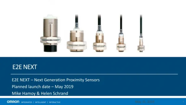
3) IR proximity range sensor • Exercise 2 What is Schmitt trigger logic? Why do we need a Schmitt trigger inverter here? CEG2400 Ch17: Sensors (v.3a)
Schmitt triggered inverter (7414)http://www.datasheetcatalog.net/de/datasheets_pdf/7/4/1/4/7414.shtml CEG2400 Ch17: Sensors (v.3a)
Frequency modulated range sensor(less sensitive to surrounding light) CEG2400 Ch17: Sensors (v.3a)
Infrared (IR) reflective proximity range sensorA reliable practical solution from Mondotronics.. CEG2400 Ch17: Sensors (v.3a) From: http://datasheet.octopart.com/3-337-Mondotronics-datasheet-7285303.pdf
Using analog-to-digital (ADC)converter • Using analog-to-digital converter to measure the distance between the lightsensor and the obstacle. • ADC=Analog to digital converter • DAC=Digital to Analog converter CEG2400 Ch17: Sensors (v.3a)
N channels range measurement using IR, multiplexer and ADC. CEG2400 Ch17: Sensors (v.3a)
Algorithm for channel selection (one of N channels) and conversion • Main() • { Init. System (GPIO , ADC). • Select channel ; • Read sensor reading by ADC. • } CEG2400 Ch17: Sensors (v.3a)
4) IR path following setup CEG2400 Ch17: Sensors (v.3a)
5) Sound sensors • Types of microphones • Moving coil microphone • Condenser microphone--- • Use ADC to convert to digital code • Input to Speech Recognition system • Clipping for simple sound detection CEG2400 Ch17: Sensors (v.3a)
Moving coil microphone (battery not required) CEG2400 Ch17: Sensors (v.3a)
Condenser microphone (more sensitive, battery required) CEG2400 Ch17: Sensors (v.3a)
Microphone with amplifier CEG2400 Ch17: Sensors (v.3a)
A digital sound recorder using ADC and DAC • Microphone: uses a uA741 op-amp to amplifier the signal • ADC circuit –An ADC (ADC0820 or ARM ADC) circuit is used to convert speech signal input into digital form. • Output Digital-to-Analog converter DAC that converts digital code into analog voltage • Output is fed to an audio power amplifier (LM386) to drive a speaker. CEG2400 Ch17: Sensors (v.3a)
Output power amplifier 5V power supply Analog output from DAC 1uF C=250uF To speaker C15=0.05uF R=10KOhms CEG2400 Ch17: Sensors (v.3a)
Algorithm to drive the digital recorder • xdata unsigned char ram_store[N], i; • record //sampling record and playback at one go • { • for(i=0; I < N ; i++) • { • ram_store[i] = read_in_sound_code_from_GPIO; • output_to_dac = ram_store[i]; • delay(); //this determines the sampling rate • } • } • playback() // playback what has been rcordered • { • for(i=0; I < N ; i++) • { • output_to_dac = ram_store[i]; • delay(); //this determines the sampling rate • } • } CEG2400 Ch17: Sensors (v.3a)
Exercises • Write the program for the interrupt method. • (II) Write the algorithm to detect the sound of a handclap or a whistle sound. • (III) What are the elements we need to implement a speech recognition system? CEG2400 Ch17: Sensors (v.3a)
Sound DC level shifterfor sound level detector CEG2400 Ch17: Sensors (v.3a)
6) Ultrasonic radar system- non invasion range detection system - Batman’s radar system Ultrasonic Transmitter | receiver picture from: http://szsaibao.taobao.com/?spm=2013.1.2-543493819.1.TCe5j8 CEG2400 Ch17: Sensors (v.3a)
The transmitter circuit CEG2400 Ch17: Sensors (v.3a)
The receiver circuit CEG2400 Ch17: Sensors (v.3a)
Method 1: Ultrasonic-radar control using MCU and timer Algortithm_radar1() //by polling { Send out pulses switch on timer Wait until echo is received. Stop timer //wait-loop Read timer, Convert time into length } Timer clock is 13824 KHz CEG2400 Ch17: Sensors (v.3a)
Method 2: Ultrasonic- radar control using interrupt and MCU’s internal timer Timer clock is 13824 KHz Video http://www.youtube.com/watch?v=qHuVhR6-Q1E CEG2400 Ch17: Sensors (v.3a)
Algorithm_radar2 : Ultrasonic- radar control using MCU interrupt and its internal timer • Algorithm_radar2 ( ) // by interrupt and timer method, tested with good result • { initialize internal_timer interrupt; • instruct the GPIO to send out pulses; • start timer; //32-bit internal timer counting at 13.824MHz; //loop • wait a while; // wait a while, the echo is expected to arrive • read internal_timer value; // result,convert into distance • } • //ISR /////////////////////////////////////////////////////////////////////////////////////// • isr2_type2_for_timer1_for_radar2 //executes when echo arrives • {Stop internal_timer; • } CEG2400 Ch17: Sensors (v.3a)
Exercises • I. Compare the two methods Algorithm_radar1( ){polling} andAlgorithm_radar2( ) {using internal timer interrupt shown above}. • II. For Algorithm_radar2( ), if the object is 3 meters away and the speed of sound is • 330m/s, what is the time-of-flight of the sound wave from the transmitter to thereceiver? • III. What is the result at the count? • IV. What is the accuracy (+-meters) of this design? What factors determine theaccuracy of this system? CEG2400 Ch17: Sensors (v.3a)
7) Temperature sensors CEG2400 Ch17: Sensors (v.3a)
8) Electromagnetic sensorElectronic compass, accuracy +/- 1 degree 2 perpendicular coils CEG2400 Ch17: Sensors (v.3a)
HMC1501 and HMC1512 Linear, Angular, and Rotary Displacement Sensor http://www.ssec.honeywell.com/magnetic/datasheets/hmc1501-1512.pdf CEG2400 Ch17: Sensors (v.3a)
9) Accelerometers • An accelerometer measures acceleration, vibration, and shock. • Example: car airbag triggering sensor, 3D mouse -- tilt sensor. • From National Instruments Corporation http://www.ni.com/products/ CEG2400 Ch17: Sensors (v.3a)
Example of using accelerometer From:http://www.csl.sony.co.jp/person/rekimoto/tilt/ Youtube Link: CEG2400 Ch17: Sensors (v.3a)
Accelerometers in WII • http://myskitch.com/keith/wii-20070724-011824.jpg/preview.jpg • IMU camera control / stabilisation Video link https://www.youtube.com/watch?v=7GVXqNLLH7Q http://youtu.be/CQ_P5XWkYcI CEG2400 Ch17: Sensors (v.3a)
Gyroscopes can be applied to building self balancing robots 2-side wheels self balancing robot Motor cycle http://www.youtube.com/watch?v=0312BNqIBFI • Our robot has one of the hottest “self balancing robots” in YouTube. • 52759 clicks on 18 Dec 2012 CEG2400 Ch17: Sensors (v.3a)
Summary • A number of different sensors have been studies • And examples of how they are used are also demonstrated CEG2400 Ch17: Sensors (v.3a)
Apenxi : Answer for Exercise for ultrasonic radar • I. Compare the two methods Algorithm_radar1( ){polling} andAlgorithm_radar2( ) {using internal timer interrupt shown above}. • II. For Algorithm_radar2( ), if the object is 3 meters away and the speed of sound is 330m/s, what is the time-of-flight of the sound wave from the transmitter to thereceiver? • Answer: sound traveled 3x2=6m. • Time_delay (dt)=6m/(330m/s)=18.18ms • If interrupt is 13.824MHz, each timer clock is 1/13.824M=72.33ns • III. What is the result at the count? • so counting result for dt=18.18ms/(1/13.824M)=18.18ms/72.33ns=251347. • IV. What is the accuracy (+-meters) of this design? What factors determine theaccuracy of this system? • Each clock pulse is (1/13.824M)s=72.33ns, that represents dL=330m/s*(72.33ns)= (330/13.824M)m=0.239mm • The real accuracy is half of it because it is an echo , so 0.239mm/2=0.119mm CEG2400 Ch17: Sensors (v.3a)