Download
1 / 31
330 likes | 492 Views
Compressed Instruction Cache. Prepared By: Nicholas Meloche, David Lautenschlager, and Prashanth Janardanan. Team Lugnuts. Introduction. We want to prove that a processor’s instruction code can be compressed after compilation, and decompressed real time during a processor’s fetch cycle.

E N D
Compressed Instruction Cache Prepared By: Nicholas Meloche, David Lautenschlager, and Prashanth Janardanan Team Lugnuts
Introduction • We want to prove that a processor’s instruction code can be compressed after compilation, and decompressed real time during a processor’s fetch cycle. • The encode/decode is performed by a software encoder and a hardware decoder.
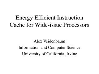
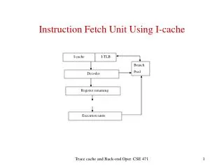
Decoder Introduction The encoder processes the machine code and compresses it. It also inserts a small set of instructions to tell the decoder how to decode. At run time, the decoder decompresses the machine code and the processor receives the original instructions. Software Hardware Compiler Assembler Processor Cache Memory Executable Compression Encoder
Motivation • Previous work has focused on either encoding instructions1, decoding instructions2, or both - but without implementation3. 1 Reference: Cool Code for Hot Risc - Hampton and Zhang 2 Reference: Instruction Cache Compression for Embedded Systems – Jin and Chen 3 Reference: A Compression/Decompression Scheme for Embedded Systems – Nikolova, Chouliaras, and Nunez-Yanez
Let’s remember this amount: the amount not stored in cache. Motivation • Fit more memory into cache at a time to decrease the likelihood of memory misses during the fetch cycle. Program Instructions Instruction Cache Loading Instructions Into Cache FETCH! CACHE FULL!
Motivation • Fit more memory into cache at a time to decrease the likelihood of memory misses during the fetch cycle. Program Instructions Now Try With Encoded Files Instruction Cache Encoder
Motivation • Fit more memory into cache at a time to decrease the likelihood of memory misses during the fetch cycle. Program Instructions Now Try With Encoded Files Instruction Cache Loading Instructions Into Cache CACHE FULL!
Motivation • Fit more memory into cache at a time to decrease the likelihood of memory misses during the fetch cycle. Program Instructions Instruction Cache More Instructions were Encoded this time!
Motivation • More code fits in cache = less cache misses. • Less cache misses = faster average fetch time. • This is useful for time critical systems such as real time embedded systems.
Hardware Design Decisions • We used a VHDL model of the LEON2 processor provided under the GNU License. • The decoder was implemented in VHDL to easily integrate it with the LEON2 processor.
Decoder Implementation • The Decoder has three modes • No_Decode – Each 32-bit fetch from memory is passed to the Instruction Fetch logic unchanged. • Algorithm_Load – The header block on code in memory is processed to load the decode algorithm for the following code. • Decode – Memory is decoded and reconstructed 32-bit instructions are passed to the Instruction fetch logic.
Decoder Implementation • A variable shifter provides the required realignment • Two lookup and shift operations are performed for each clock cycle to produce one 32 bit result per cycle • The Decoder contains input buffering to ensure one instruction output per clock cycle unless there are sustained uncompressible instructions in the input.
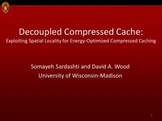
CAM sample path PC Increment Logic PC Increment Out Register Data in Shift Logic Shift 16 Logic Shift Logic Shift 16 Logic 128 x 20 RAM TCAM 128 x 20 RAM TCAM Mux Mux 16 bits 16 bits Decoded Instruction
Decoder Implementation • The core of the Decoder is a CAM (Content Addressable Memory) • 8 bits of the incoming code is used to address the CAM
CAM sample path PC Increment Logic PC Increment Out Register Data in Shift Logic Shift 16 Logic Shift Logic Shift 16 Logic 128 x 20 RAM TCAM 128 x 20 RAM TCAM Mux Mux 16 bits 16 bits Decoded Instruction
Decoder Implementation • The core of the Decoder is a CAM (Content Addressable Memory) • 8 bits of the incoming code is used to address the CAM • The CAM returns a corresponding 16 bit decode
CAM sample path PC Increment Logic PC Increment Out Register Data in Shift Logic Shift 16 Logic Shift Logic Shift 16 Logic 128 x 20 RAM TCAM 128 x 20 RAM TCAM Mux Mux 16 bits 16 bits Decoded Instruction
Decoder Implementation • The core of the Decoder is a CAM (Content Addressable Memory) • 8 bits of the incoming code is used to address the CAM • The CAM returns a corresponding 16 bit decode • The CAM also returns the required shift to left-align the next encoded instruction
CAM sample path PC Increment Logic PC Increment Out Register Data in Shift Logic Shift 16 Logic Shift Logic Shift 16 Logic 128 x 20 RAM TCAM 128 x 20 RAM TCAM Mux Mux 16 bits 16 bits Decoded Instruction
Encoding Scheme The computer is no better than its program. ~ Elting Elmore Morison
Encoder Implementation • The encoder was created in C++. • It chooses an encoding scheme based on an analysis of the file content. • The input file is a set of instructions for the LEON2 processor, and the output is the set of encoded instructions for the decoder to decode. • The encoder adds a set of instructions to the beginning of each output file. This communicates the decoding algorithm.
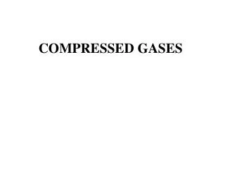
…. A lot! Encoding Algorithm • We experimented with using a Huffman Tree to encode the files. A B A C B C But with a Huffman Tree, the encoding can become 2N bits deep (where N is the number of bits encoded)
…. A lot! Encoding Algorithm • We experimented with using a Huffman Tree to encode the files. A B C But with a Huffman Tree, the encoding can become 2N bits deep (where N is the number of bits encoded)
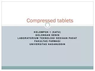
Since A, B, and C are still common, and encoded in a short number of bits, we still get savings! Encoding Algorithm • We experimented with using a Huffman Tree to encode the files. A B C Uncompressed Case Instead we cut the tree off short and lump everything below the point into an “uncompressed” case
Encoding Implementation • Empirical evidence suggested we encode 16 bits at a time. • We chop off our Huffman tree at a tree depth of 8 (8 bits final encoding). • Uncompressed code is 8 encode bits + the original 16 bits for a total of 24 bits. We make up for this with other compression.
Encoding Implementation • 3 pass encoding. • First pass – Analyze instructions in 16 bit chunks and record locations of branch instructions and targets.
Encoding Implementation • Second pass – Encode the instructions. • Place the target addresses at the beginning of a new instruction word. • Leave Jump algorithms un-encoded. Analyze where new target instructions will be located. • Third Pass – Write the encoding to an output file.
Compression Analysis • We used test instruction sets that came with the VHDL LEON2 processor GNU licensing.
~ 5%-12% Results • We are seeing 5% to 12% savings in instructions size. • More compression could be realized if the algorithm descriptions are compressed
Conclusions • There is an obtainable gain by pursuing compression this way. • Hardware implementation is unobtrusive. • A compiler could include the encoder after link time easily. • Savings is positive.
Questions? Team Lugnuts