Download
1 / 21
210 likes | 369 Views
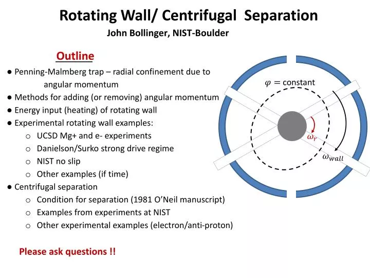
Rotating Wall/ Centrifugal Separation. John Bollinger, NIST-Boulder. Outline. ● Penning- Malmberg trap – radial confinement due to angular momentum ● Methods for adding (or removing) angular momentum ● Energy input (heating) of rotating wall ● Experimental rotating wall examples :

E N D
Rotating Wall/ Centrifugal Separation John Bollinger,NIST-Boulder Outline • ● Penning-Malmberg trap – radial confinement due to • angular momentum • ● Methods for adding (or removing) angular momentum • ● Energy input (heating) of rotating wall • ● Experimental rotating wall examples: • UCSD Mg+ and e- experiments • Danielson/Surko strong drive regime • NIST no slip • Other examples (if time) • ● Centrifugal separation • Condition for separation (1981 O’Neil manuscript) • Examples from experiments at NIST • Other experimental examples (electron/anti-proton) constant Please ask questions !!
Penning-Malmberg trap – radial confinement due to angular momentum ●axial confinement ↔ conservation of energy ● radial confinement ↔ conservation of angular momentum O’Neil, Dubin, UCSD Axial asymmetries produce increases in
Radial expansion (or spin-down) due to asymmetries From T.B. Mitchell et al., in Trapped Charged Particles and Fundamental Physics (1999), p. 309. rotation frequency determined from plasma shape 2zo r ● For laser-cooled plasmas in NIST Penning trap (Rp << Rtrap): Critical asymmetry produced by (B field)-(trap symmetry axis) misalignment r ● B-field and trap symmetry axis aligned to better than 0.01o by minimizing zero-frequency mode excitation 2ro
Methods for adding (or removing) angular momentum • Sideband drive techniques/ axialisation (see January 16 presentation by Segal) • quadrupole drives at ωz+ωm or Ωc=(Ωc-ωm)+ωm (with damping on ωz , Ωc ) • single particle techniques that work well at low space charge y laser beam 2. Radiation pressure from a laser (laser torque) plasma boundary in x-y plane x 3. Rotate the trap wr - more practically, apply a rotating electric field asymmetry Rotating wall perturbations: m=2 m=1 0o 120o 0o 60o 240o 240o 300o 120o 360o 120o 180o 240o
rotating wall potential simulation - Brian Sawyer, NIST
Work due to rotating wall = ambient torque due to field errors , background gas collisions, .. = torque applied by the rotating electric field and increases ●steady state confinement requires Work due to rotating wall under steady state conditions ambient torques determine energy input (heating) due to the rotating wall application of the rotating wall requires cooling !! Can the applied torques and cooling be sufficiently strong for the rotating wall to work?
Rotating Wall/ Centrifugal Separation John Bollinger,NIST-Boulder Outline • ● Penning-Malmberg trap – radial confinement due to • angular momentum • ● Methods for adding (or removing) angular momentum • ● Energy input (heating) of rotating wall • ● Experimental rotating wall examples: • UCSD Mg+ and e- experiments • Danielson/Surko strong drive regime • NIST no slip • Other examples (if time) • ● Centrifugal separation • Condition for separation (1981 O’Neil manuscript) • Examples from experiments at NIST • Other experimental examples (electron/anti-proton) constant
UCSD Mg+ and e- experiments PRL 78, 875 (1997); PRL 81, 4875 (1998); POP 7, 2776 (2000) Central density compression by RW coupling to modes ●39 electrons or 109 Mg+ ions ●e- cyclotron cooling; weak Mg+-neutral cooling (0.1 s-1) ● or rotating wall applied near ends of plasma ●Strong torques applied by RW coupling to modes
UCSD Mg+ and e- experiments PRL 78, 875 (1997); PRL 81, 4875 (1998); POP 7, 2776 (2000) ●39 electrons or 109 Mg+ ions, B=4 T ●e- cyclotron cooling; weak Mg+-neutral cooling (0.1 s-1) ● or rotating wall applied near end of plasma ●strong torques applied by RW coupling to modes ● significant compression observed with both e- and Mg+ ●steady state confinement for weeks ●non-zero slip ; plasma mode frequency coupling to the rotating wall ● maximum compression (density 109 cm-3) limited by and heating
Danielson/Surko strong drive regime PRL 94, 035001 (2005); POP 13, 055706 (2006); PRL 99, 135005 (2007) steady density vs applied RW frequency weak wall (0.1 V) vs strong wall (1.0 V) ●9 e-, B=5 T, e- cyclotron cooling s-1 ● rotating wall applied near end of plasma ●weak wall (0.1 V) compression at distinct frequencies, consistent with coupling to modes 1 V 0.1 V ● strong wall (1 V) compression at all frequencies, no apparent slip
Danielson/Surko strong drive regime PRL 94, 035001 (2005); POP 13, 055706 (2006); PRL 99, 135005 (2007) MHz steady density vs applied RW frequency weak wall (0.1 V) vs strong wall (1.0 V) ●9 e-, B=5 T, e- cyclotron cooling s-1 ● rotating wall applied near end of plasma ●weak wall (0.1 V) compression at distinct frequencies, consistent with coupling to modes 1 V 0.1 V ● strong wall (1 V) compression at all frequencies, no apparent slip ● critical drive strength observed ● maximum density cm-3 ● strong drive regime characterized by independent of , ● increased cyclotron cooling, lower outward transport enabled access to strong drive regime
NIST phase-locked rotating wall Huang et al., PRL 80, 73 (1998); POP 5, 1656 (1998) ● 102<N<106 laser-cooled Be+ ions ● T < 10 mK ● compression and no slip observed with both and walls ● rotating wall applied uniformly across axial extent of plasma !!
NIST phase-locked rotating wall Huang et al., PRL 80, 73 (1998); POP 5, 1656 (1998) time-averaged Bragg scattering strobed ● 102<N<106 laser-cooled Be+ ions ● T < 10 mK ● compression and no slip observed with both and walls ● rotating wall applied uniformly across axial extent of plasma !! ● in steady state rotating wall and plasma (crystal) rotation are phase coherent
NIST phase-locked rotating wall Huang et al., PRL 80, 73 (1998); POP 5, 1656 (1998) ●Torque mechanism for wall with crystalized plasma easy to understand ● wall changes the potential in the rotating frame ●Plasma shape is a tri-axial ellipsoid; rotating boundary applies torque; shear forces in crystal transmit forces to interior top-view image of a planar crystal showing distortion of the radial boundary with an
NIST phase-locked rotating wall Huang et al., PRL 80, 73 (1998); POP 5, 1656 (1998) ● Why does the (dipole) wall work?? ● A uniform electric field only drives a center-of-mass motion for a single species plasma in a quadrupole trap Tutorial problem: prove this ● impurity ions can couple a uniform electric field to internal degrees of freedom Monte Carlo simulation of equilibrium distribution of a two species plasma with 1000 particles (88% Be+, 12% m=26 u) Dubin 1998 centrifugal separation is asymmetric
Other examples of rotating wall compression ● mixed e-/pbar plasmas From Andresen et al., PRL 100, 203401 (2008) ● other examples ??
Rotating Wall/ Centrifugal Separation John Bollinger,NIST-Boulder Outline • ● Penning-Malmberg trap – radial confinement due to • angular momentum • ● Methods for adding (or removing) angular momentum • ● Energy input (heating) of rotating wall • ● Experimental rotating wall examples: • UCSD Mg+ and e- experiments • Danielson/Surko strong drive regime • NIST no slip • Other examples (if time) • ● Centrifugal separation • Condition for separation (1981 O’Neil manuscript) • Examples from experiments at NIST • Other experimental examples (electron/anti-proton) constant
Condition for centrifugal separation T.M. O’Neil, Phys. Fluids 24, 1447 (1981) Consider two species q1,m1 and q2, m2 thermal equilibrium both species evolve to same only difference is centrifugal potential ● Centrifugal separation important if: [centrifugal force difference][size of plasma] > kBT ● Centrifugal separation is complete if:
Observations of centrifugal separation ● conditions for centrifugal separation readily satisfied with laser cooling ● Larson et al., PRL 57, 70 (1986) – sympathetically cool Hg+ ions with laser-cooled Be++ B B ● “missing volume” in laser cooled plasmas ● other laser-cooled plasma examples Be+-ion Imajo et al., PRA 55, 1276 (1997) Gruber et al., PRL 86, 636 (2001) Be+- e+ Jelenkovic et al., PRA 67, 063406 (2003)
Centrifugal separation with e- and pbar ●Gabrielse, et al., PRL 105, 213002 (2010). measured pbar radius looking for pbar loss when B=3.7 T ramped to 1 T ● Andresen, et al., PRL 106, 145001 (2011). measured separation directly though imaging measured time scale for separation to occur !! 1 T 3 T Add pbar slug to center of e- plasma
An interesting tutorial problem 9Be+, 27Al3+ laser-cooled Be+ sympathetically cools 27Al3+ a strongly coupled 2-component plasma ?? Calculate the rotation frequency ωr required for mixing of the 9Be+, 27Al3+ species at a temperature of 10 mK? mBe = 8.942mp mAl= 26.772mp Rp= 1 mm