Download

1 / 29
310 likes | 482 Views
Principles of Superconducting Accelerator Magnet Design Herman ten Kate. CERN Accelerator School on Superconductivity for Accelerators, Erice, 29 April 2013. Content. HEF synchrotron & what is a good magnet Magnetic design

E N D
Principles of Superconducting Accelerator Magnet DesignHerman ten Kate CERN Accelerator School on Superconductivity for Accelerators, Erice, 29 April 2013
Content • HEF synchrotron & what is a good magnet • Magnetic design • Relevant issues, a tour from filament to vacuum vessel • Few topics: Field and Field quality, Minimum Engineering Current Density, Grading, Training, High Currents, a 20T design. • Conclusion • Try to do : following the Superconductor Properties (Larbalestier, Flukiger) • and Basics of Accelerator Optics (Holzer) • to introduce the Concepts and Issues of Accelerator Magnets • to prepare for the more in-depth presentations on Cables (Bruzzone), Magnetic Design (Todesco), Mechanical Design (Toral), • Thermal design (Baudouy) and Cryostats (Parma).
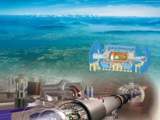
1. Superconductivity and HE Physics Accelerators, like LHC, can not be realized without extensive use of superconductivity and high quality magnets Nb/Cu cavities for acceleration 1232 dipoles magnets for bending 386 quadrupole magnets for focusing ~7000 Correction magnets ATLAS and CMS detector magnets Insertion and Final Focusing magnets No Higgs without Superconductivity!
What is a good magnet? • It technically performs: generates magnetic field in the required space, dipoles, quadrupoles, multi-pole correction magnets, while respecting space uniformity and time stability requirements; all requiring a proper magnetic design. • It’s safe: respecting mechanical and electrical design codes, negligible magnetic stray field, no cryogenic blasts, a sound quench protection as well as reliable instrumentation and controls. • It’s available: has to fulfill stability, training & degradation requirements. • And at minimum cost: robust and simple design suitable for series production within a foreseeable time, easy to operate, well managed. • Often one or more of these requirements, in particular regarding training, robustness and costs are not fulfilled, hindering accelerators today to run far beyond 8T level………..you are challenged to fix this.
From Material to Magnet….. • For making good magnets we need to understand in depth and able to control the entire chain of development from lattice & grains, through wires and cabling, to coil winding, - assembly, cryostating, protection and proper controls…… • Main issue in how to make performing multi-kA conductors and make coil windings that guarantee the magnet not to quench or degrade ? Lattice Filament Wire Cable Magnet 50 nm 12 mm 20 µm 1 mm 15 meter
I 2. Magnetic design: stay on orbit • Need a Lorentz force acting on the particles in the “beam” (e, p, heavy ions) • by a uniform B across the beam section (dipole magnets) • How? Fill parallel walls or intersection ellipses with uniform Jeng=Jo or put a Jeng=Jo.cosθ on a cylinder. • Parallel walls Intersecting ellipses Cosθ (Roma arc) Practical 2 layer coil • Either way B ≈ 0.5 µo Jo w or 0.25T/mm coil width assuming 400A/mm2 • 8T with ~33mm 16T with ~66 mm 24T with ~100mm • (excluding effect of iron yoke which is modest, another + 0.3-0.8%)
Quads for squeezing • Second type of magnets required are focusing magnets. • Bringing diverging particles back on track, focusing, requires Lorentz forces linearly increasing with distance from the beam center. • Such quadrupole magnets can be made by arranging 4 poles on a cylinder following in good approximation Jeng=Jo.cos2θ • The technology is similar to dipole • magnets though the effort is on • achieving maximum magnetic • field gradients
Practical solutions • From an ideal cos(θ) dipole or cos(2θ)quadrupole to a practical solution, arranging windings in blocks to fulfill field quality requirements. practical dipole windings pack practical quadrupole windings pack Courtesy of L.Bottura
Limits in collision energy • Beams are crossed with low angle at points were collisions take place, the place where the customer of “the machine”, the physicists sit with their physics experiment. • Collision energy is limited by bending magnetic field and radius of the synchrotron following • Which immediately links physics discovery potential at higher energy to superconducting material B(J) and footprint 2R of the machine….& cost. • There are clear thresholds in the combinations of superconductor used Jengc(B) and tunnel length. • Examples: LHC: 14 TeV: NbTi at 8 - 9T, tunnel length ≈30km • 100 TeV: Nb3Sn at 15 -16T, ≈130km • 200 TeV: HTS at 20-25T, ≈200km • So we need good magnets, what are the issues….
3. A walk from inside to outside • A wire embedding superconducting material in a matrix. • A cable with many coated strands and with insulation. • Coil windings comprising a stack of cables and wedges. • A coil with windings, ground insulation and helium cooling. • A laminated collar pack surrounding the coils, transparent for Helium. • A laminated yoke in between collars and support cylinder. • A support cylinderalso helium can with ends and transfer ports. • A cryostat with vacuum vessel, thermal shield, cold mass supports, bus bars, helium lines and instrumentation ports.
3.1 Wire with Superconductor • A wire with a matrix embedding superconducting material (see presentations of D.Larbalestier and R.Flukiger). • NbTi wire, good for 8 - 9T at 1.9K • Nb3Sn wire, good for 14 -16T at 1.9K • B2212 wire, good for 17->30T at 4.2K • Re123 tape, good for 17->30T at 4.2K • What counts is • Engineering current density Jeng(B,T,Ɛ) of ~400A/mm2 • and Temperature margin ΔTmargin= Tcs(B,I)-Tbath of >2-5K • to arrive at target B in a cost efficient way. • Filament diameter <50µm to warrant filament stability and <5µm to limit field errors in NbTi and <40µm in Nb3Sn • Twist pitch of ~20-30mm to limit ramp losses • Wire diameter <1.3mm to avoid self-field instability
3.2 Cables with strands • Highly compacted Rutherford cable with 20-50 strands, fully transposed. • Cable width 12-24mm depending on cable current, number of layers. • Key-stoned section to accommodate cos-θ type winding blocks. • Coating on strand (SnAg,Ni,Cr) to limit and control interstrand loss and cable magnetization, or avoid sintering (Nb3Sn). • Cable pitch of ~100-200mm to limit ramp loss, cable integrity & stiffness. • Superfluid Helium in NbTi cable voids at 1.9K to enhance enthalpy. • For Nb3Sn, no He in cable but vacuum impregnated to freeze wire movement and reduce wire-to-wire point strain. • 3-4 x 0.4mm2 Re123 tapes in Roebel type cables or may be in CORC. • So far no Cable-in-conduit-Conductors used in accelerator magnets but possible……..may be a way to get helium cooling directly on the Nb3Sn strands and solve the training issue in these magnets.
I I I B 3.3 Coils with cables and wedges • Blocks of cable-turns, Cu wedges in-between, to control field errors. • Two layers or even more, 4, 6. • Cable insulation (NbTi: Kapton/glass tapes; Nb3Sn: glass tapes, glass/mica, glass braid • A dielectric film included is preferred to avoid risk of shorts in series production. • Ground insulation (usually thick Kapton). • Coil layer helium cooling (fishbone). • Cooling in-between layers if high heat load. • Windings superfluid He transparent at 1.9K (NbTi) or vacuum impregnated (Nb3Sn). • Coil instrumentation: voltage taps, temperature sensors, strain and pressure sensors, quench heaters.
3.4 Coils ends • Coil ends with end-spacers: different layouts for cosθ coils and block coils. • In either design this is a weak area causing premature quenching/training. • Axial wedges “connected” to end spacers, mechanically not uniform, different materials, gaps by fabrication and winding tolerances. • A continuous and ”natural” support has to be aimed at, still lot of discussion on best solutions.
3.5 Collars, Yoke and Cylinder • A laminated collar pack surrounding the coils • Provides structural precision and is spacer to yoke, • transfers the Lorentz forces to yoke and cylinder. • Plates of stamped SS or Al alloy. • Two halves, key locked or single ring shrink-fitted. • Also bladder techniques are uses to lock & pre-stress. • Collar plates are spaced, so open for sf Helium. • A laminated iron yoke in between collars and • support cylinder • Iron yoke plates, field enhancement & spacer • to support cylinder. • Support cylinder and helium can with ends • Reacts the Lorentz forces (100-200t/m) by elastic tensile stress. • Shapes the helium bath.
3.6 Cold mass in Cryostat • A cryostat with vacuum vessel, thermal shield, cold mass supports, bus bars, helium lines (for 1.9 or 4K cooling) and instrumentation ports. • Normal steel vacuum vessel. • Aluminum alloy thermal shield with cooling tubes and layers of MLI. • Cold mass supports to take the weight, 1 fixed, others sliding. • Instrumentation and cables. • Bus lines and at either side, interconnections to neighboring coils.
4.1 Field and Field Quality • Magnetic field of a “dipole” magnet, the mainly determined by: • Current density and coil width, B ≈ 0.5 µo Jo w • Iron contribution by the yoke, some +5-10%, which • can analytically be estimated using the mirror method. • Full precision with the FEA codes, ANSYS, TOSCA, Roxie & more. • Magnetic Field quality across the beam is affected by: • Shape of coils with optimized but not perfect layout of cables & wedges. • Deflection of the coils under Lorentz force, try to limit to ~50µm. • Presence and local shape of the iron facing the coil. • Boundary induced coupling currents in the cables. • Shape and thickness of the filaments in the wire. • All this is well understood and implemented in dedicated design codes.
4.2 Efficient design: current density • Efficient = cost effective design as well! • B ≈ 0.5 µo Jo w • ----> Need maximum Jeng and minimum w • J: for a target field B we need coils to operate at • Jeng: ~400 A/mm2 at this B (8, 16, 24…T) ! • Given the required margin (~40-50% of Ic, 70-80% on load line) we need • Jeng_c of ~800-1000 A/mm2 in the conductor! • tough already with NbTi and Nb3Sn at 1.9K • not yet achieved in B2212 (~550 A/mm2@25T) • nor in and Re123 (~350 A/mm2@25T) • Today a factor 2-3 missing and no real long production lengths available yet.
Efficient design: current density • Jeng_c > 800A/mm2 not yet achieved in Re123 and Bi-2212 at 20-30T! • Need a factor 2-3 more, at least !
4.3 Efficient design: grading • Width of windings / number of layers in coil: • Number of layers is cost driver as the coil winding/impregnation&stacking process is labor intensive: minimize number of layers. • Achievable is 2 for 8T(NbTi) -13T(Nb3Sn) level, 3-4 for 13-16T (Nb3Sn). • Grading: • Same cable width in all layers and same Jc is not cost optimal, apply grading to have roughly the same margin in all layers at Bpeak/layer. • Example: MSUT(1995): 1m Nb3Sn dipole, 50mm bore LHC type, 11.3T@4.2K at first cool down and first quench, showed no training. Inner layer: 33 Nb3Sn PIT strands dia 1.26mm cable size 1.98/2.47 x 21.8 mm2 Outer layer: 33 Nb3Sn PIT strands dia 1.00mm cable size 1.98/2.47 x 17.4 mm2
4.4 Safe: High Current Cables • Magnetic field and stored energy • Magnetic fieldB N.I • Stored energy E B2.Volume • Inductance L N2 • We need safe survival from a quench. • Energy dump within short time • before conductor burns out. • Also magnet ramps up and down with acceptable low voltage. • Thus low N, high current I • Also Isafe J E / Vd, requiring <kV-range for Vd, • with usual current densities, this leads to 10-100 kA. • Given strand currents of typically 100 to 500A, we need for large scale magnets multi strand cables of 20-1000 strands, • No escape!
Scaling Isafe J x B2 x Volume 2 m3200-800 A 25 m38 kA 0.0001 m3200 A 50m312 kA 400 m320 kA 1000 m3I 40-70 kA
Quest for high current conductors • One cannot build large scale magnets from single NbTi, Nb3Sn, Bi-2212, or Re123 wires or tapes. • We need superconductors that can be cabled and survive a quench! 200 A HTS tape Not useful when not cabled 65000 A@5T Al-NbTi/Cu This works! ATLAS Barrel Toroid @ CERN
4.5 Example of a 20T design • A flavor of what would be possible in principle, a hybrid design with NbTi, Nb3Sn and Bi-2212 ! • Based on ~380 A/mm2 (~200A/mm2 in low-q Nb3Sn) one can make 20T in 90mm width, • in a twin dipole of ~800mm diameter. • Coil stress <200MPa, looks makeable. • But need much better Bi-2212 at lower cost. • Actually a new R&D effort just started at CERN to invent novel, innovative and practical solutions…… Courtesy of E.Tedesco
4.6 Training in Nb3Sn magnets • Nb3Sn dipole/quadrupole coils tend to train heavily, in far too many steps and with relative low value of first quench, why, how to solve? • For a real accelerator magnet, a long training, de- and re-training are unacceptable, nominal current, say 80% on load line, should be reached in < 3 steps. HD1 LBNL D20 LBNL Examples of long training in Nb3Sn magnets
4.6 Training and Cable Stability • A possible explanation: • NbTi cables are transparent for sf He at 1.9K, helps to remove heat and increase enthalpy. This causes collective strands stability to be effective at I/Ic < 0.7-0.8 • Nb3Sn windings are impregnated, to suppress wire motion and create “hydrostatic” pressure on the brittle strands to avoid Jc degradation. Thus a Nb3Sn cable is less stable at 1.9K and behaves as single strand down to I/Ic=0.4. • Meaning: we need more superconductor in Nb3Sn cables to have the same minimum quench energy MQE, 80% on the load line is too much ! Point-like MQE measured on comparable Nb3Sn and NbTi cables.
5. Conclusion • Design principles are well known and understood, but success often depends on the details, in particular in the coil windings. • For NbTi based magnets the challenge is to operate stable and predictable at high I/Ic, scaling up to wider bores and developing special versions like for high-ramp rate magnets. • For Nb3Sn the primary and urgent goal is to understand and control training in order to break through the practical limit of today of ~11T and demonstrate full length series production in the 11-16T range. • R&D towards designs for 20-25T using HTS are in progress, thinkable solutions in terms of coil layouts (Hybrids) are present and look makeable, but yet to be demonstrated. • Investments are needed in raising the engineering current density in Bi-2212 and Re123 (factors 2-3), delivery of uniform km long production units, a proven cable technology, and a fast and elegant quench protection, and reducing cost, the kA/m price at 20T/4K, of coarse….