Download
1 / 47
470 likes | 725 Views
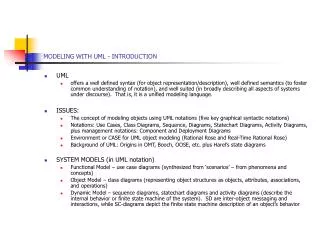
Chapter 2 Object-Oriented Software Engineering: Using UML, Patterns, and Java, 2 nd Edition By B. Bruegge and A. Dutoit Prentice Hall, 2004. Modeling with UML. Modeling with UML. What is UML? Use case diagrams Class diagrams Sequence diagrams Statechart diagrams Activity diagrams.

E N D
Chapter 2 Object-Oriented Software Engineering: Using UML, Patterns, and Java, 2nd Edition By B. Bruegge and A. Dutoit Prentice Hall, 2004. Modeling with UML
Modeling with UML • What is UML? • Use case diagrams • Class diagrams • Sequence diagrams • Statechart diagrams • Activity diagrams
What is modeling? • Modeling is a means of dealing with complexity. • Modeling consists of building an abstraction of reality. • Abstractions are simplifications because: • They ignore irrelevant details and • They only represent the relevant details. • What is relevant or irrelevant depends on the purpose of the model.
Why build models in software engineering? • Software is getting increasingly more complex • Windows XP > 40 million lines of code • A single programmer cannot manage this amount of code in its entirety. • Code is not easily understandable by developers who did not write it • We need simpler representations for complex systems • Modeling is a mean for dealing with complexity
What to Model? • We need models of the application and solution domains. • Application Domain (Requirements Analysis): • The environment in which the system is operating • Application domain models help us define the problem • Solution Domain (System Design, Object Design): • The available technologies to build the system • Solution domain models help us address the problem systematically
What is UML? • UML (Unified Modeling Language) • An emerging standard for modeling object-oriented software. • Resulted from the convergence of notations from three leading object-oriented methods: • OMT (James Rumbaugh) • OOSE (Ivar Jacobson) • Booch (Grady Booch) • Reference: http://www.uml.org • Supported by several CASE tools • Rational ROSE • TogetherJ
UML: First Pass • You can model 80% of most problems by using about 20 % UML • We teach you those 20%
UML First Pass • Use case diagrams • Describe the functional behavior of the system as seen by the user. • Class diagrams • Describe the static structure of the system: Objects, Attributes, Associations • Sequence diagrams • Describe the dynamic behavior between actors and the system and between objects of the system • Statechart diagrams • Describe the dynamic behavior of an individual object (essentially a finite state automaton) • Activity diagrams • Model the dynamic behavior of a system, in particular the workflow (essentially a flowchart)
Watch ReadTime SetTime WatchUser WatchRepairPerson ChangeBattery UML first pass: Use case diagrams Use case Package Actor Use case diagrams represent the functionality of the system from user’s point of view
1 1 1 2 1 1 LCDDisplay Battery load Time now blinkIdx blinkSeconds() blinkMinutes() blinkHours() stopBlinking() referesh() UML first pass: Class diagrams Class diagrams represent the structure of the system Association Class Multiplicity Watch 1 2 PushButton state push()release() Attribute Operations
:Watch :LCDDisplay :Time :WatchUser pressButton1() blinkHours() pressButton1() blinkMinutes() pressButton2() incrementMinutes() refresh() pressButtons1And2() commitNewTime() stopBlinking() UML first pass: Sequence diagram Actor Object Message Activation Lifeline Sequence diagrams represent the behavior as interactions
UML first pass: Statechart diagrams for objects with interesting dynamic behavior State Event Initial state Transition Final state Represent behavior as states and transitions
Other UML Notations UML provide other notations that we will be introduced in subsequent lectures, as needed. • Implementation diagrams • Component diagrams • Deployment diagrams • Introduced in lecture on System Design • Object constraint language • Introduced in lecture on Object Design
UML Core Conventions • Rectangles are classes or instances • Ovals are functions or use cases • Instances are denoted with an underlined names • myWatch:SimpleWatch • Joe:Firefighter • Types are denoted with non underlined names • SimpleWatch • Firefighter • Diagrams are graphs • Nodes are entities • Arcs are relationships between entities
Used during requirements elicitation to represent external behavior Actors represent roles, that is, a type of user of the system Use cases represent a sequence of interaction for a type of functionality The use case model is the set of all use cases. It is a complete description of the functionality of the system and its environment Passenger PurchaseTicket Use Case Diagrams
An actor models an external entity which communicates with the system: User External system Physical environment An actor has a unique name and an optional description. Examples: Passenger: A person in the train GPS satellite: Provides the system with GPS coordinates Passenger Actors
A use case represents a class of functionality provided by the system as an event flow. A use case consists of: Unique name Participating actors Entry conditions Flow of events Exit conditions Special requirements PurchaseTicket Use Case
Name:Purchase ticket Participating actor:Passenger Entry condition: Passenger standing in front of ticket distributor. Passenger has sufficient money to purchase ticket. Exit condition: Passenger has ticket. Event flow: 1. Passenger selects the number of zones to be traveled. 2. Distributor displays the amount due. 3. Passenger inserts money, of at least the amount due. 4. Distributor returns change. 5. Distributor issues ticket. Use Case Description: Example
<<extends>> relationships represent exceptional or seldom invoked cases. The exceptional event flows are factored out of the main event flow for clarity. Use cases representing exceptional flows can extend more than one use case. The direction of a <<extends>> relationship is to the extended use case Passenger PurchaseTicket <<extends>> OutOfOrder TimeOut <<extends>> <<extends>> <<extends>> Cancel NoChange The <<extends>> Relationship
<<includes>> relationship represents behavior that is factored out of the use case. <<includes>> behavior is factored out for reuse, not because it is an exception. The direction of a <<includes>> relationship is to the using use case (unlike <<extends>> relationships). Passenger PurchaseMultiCard PurchaseSingleTicket <<includes>> <<includes>> NoChange Cancel CollectMoney <<extends>> <<extends>> The <<includes>> Relationship
Use Case Diagrams: Summary • Use case diagrams represent external behavior • Use case diagrams are useful as an index into the use cases • Use case descriptions provide meat of model, not the use case diagrams. • All use cases need to be described for the model to be useful.
zone:Zone Price: Price TarifSchedule Trip Class Diagrams • Class diagrams represent the structure of the system. • Used • during requirements analysis to model problem domain concepts • during system design to model subsystems and interfaces • during object design to model classes. Enumeration getZones() Price getPrice(Zone) * *
TarifSchedule TarifSchedule TarifSchedule Table zone2price Enumeration getZones() Price getPrice(Zone) zone2price getZones() getPrice() Classes Name Signature Attributes Operations • A class represent a concept • A class encapsulates state (attributes) and behavior (operations). • Each attribute can have a type. • Each operation can have a signature. • The class name is the only mandatory information.
tarif_1974:TarifSchedule Instances zone2price = { {‘1’, .20},{‘2’, .40}, {‘3’, .60}} • An instance represents a phenomenon. • The name of an instance is underlined and can contain the class of the instance. • The attributes are represented with their values.
Actor vs Instances • What is the difference between an actor, a class and an instance? • Actor: • An entity outside the system to be modeled, interacting with the system (“Passenger”) • Class: • An abstraction modeling an entity in the problem domain, must be modeled inside the system (“User”) • Object: • A specific instance of a class (“Joe, the passenger who is purchasing a ticket from the ticket distributor”).
TarifSchedule TripLeg Associations Enumeration getZones() Price getPrice(Zone) PriceZone * * • Associations denote relationships between classes. • The multiplicity of an association end denotes how many objects the source object can legitimately reference.
1-to-1 and 1-to-many Associations Has-capital Country City 1 1 name:String name:String One-to-one association Point * Polygon x: Integer y: Integer draw() One-to-many association
Many-to-Many Associations Lists * * StockExchange Company SX_ID tickerSymbol Lists Company 1 1 StockExchange SX_ID tickerSymbol
From Problem Statement To Object Model Pr oblem Statement: A stock exchange lists many companies. Each company is uniquely identified by a ticker symbol Class Diagram: Company * * StockExchange Lists tickerSymbol
Exhaust system TicketMachine ZoneButton 0..2 1 Muffler Tailpipe diameter diameter Aggregation Exhaust system 0..2 1 Muffler Tailpipe diameter diameter • An aggregation is a special case of association denoting a “consists of” hierarchy. • The aggregate is the parent class, the components are the children class. • A solid diamond denotes composition, a strong form of aggregation where components cannot exist without the aggregate. (Bill of Material) 3
Without qualification File 1 * Directory filename With qualification 1 0…1 Directory filename File Qualifiers • Qualifiers can be used to reduce the multiplicity of an association.
CancelButton ZoneButton Button Inheritance • The children classes inherit the attributes and operations of the parent class. • Inheritance simplifies the model by eliminating redundancy.
DispatcherInterface Notification IncidentManagement Packages • A package is a UML mechanism for organizing elements into groups (usually not an application domain concept) • Packages are the basic grouping construct with which you may organize UML models to increase their readability. • A complex system can be decomposed into subsystems, where each subsystem is modeled as a package • Packages show system and/or subsystem boundaries, thus clarifying the interfaces between a user and the system or between subsystems.
Used during requirements analysis To refine use case descriptions to find additional objects (“participating objects”) Used during system design to refine subsystem interfaces Classes are represented by columns Messages are represented by arrows Activations are represented by narrow rectangles Lifelines are represented by dashed lines TicketMachine Passenger selectZone() insertCoins() pickupChange() pickUpTicket() UML sequence diagrams
TarifSchedule Display Passenger selectZone() lookupPrice(selection) displayPrice(price) price Nested activations ZoneButton Dataflow • The source of an arrow indicates the activation which sent the message • An activation is as long as all nested activations • Horizontal dashed arrows indicate data flow • Vertical dashed lines indicate lifelines …to be continued...
CoinIdentifier Display CoinDrop Passenger insertChange(coin) lookupCoin(coin) price displayPrice(owedAmount) [owedAmount<0] returnChange(-owedAmount) Iteration & condition …continued from previous slide... ChangeProcessor * Iteration Condition • Iteration is denoted by a * preceding the message name • Condition is denoted by boolean expression in [ ] before the message name …to be continued...
Passenger createTicket(selection) Ticket print() free() Creation and destruction …continued from previous slide... Creation ChangeProcessor Destruction • Creation is denoted by a message arrow pointing to the object. • Destruction is denoted by an X mark at the end of the destruction activation. • In garbage collection environments, destruction can be used to denote the end of the useful life of an object.
Sequence Diagram Summary • UML sequence diagram represent behavior in terms of interactions. • Useful to find missing objects. • Time consuming to build but worth the investment. • Complement the class diagrams (which represent structure).
State Chart Diagrams State Initial state Event Transition Final state Represent behavior as states and transitions
State Chart Elements • State • A condition satisfied by the attributes of an object • Transition • A change of state • Triggered by events • Inside a state • Activity • Behavior that is executed as long as an object resides in some state • Internal transition • A transition that does not leave the state • Nested statecharts • A statechart inside a state
Ringing Timeout/Keep ringing Collecting digit Digit/Analyze digit Enough digits/Connect Ringing Busy Dialtone Offhook Talking No dialtone Collecting digits State Chart Example: Making a phone call Pick up Idle Press digit Line out of service Line in service Hang up Press digit Circuit not available Hang up Circuit available Hang up Pick up
Activity Diagrams • An activity diagram shows flow control within a system • An activity diagram is a special case of a state chart diagram in which states are activities (“functions”) • Two types of states: • Action state: • Cannot be decomposed any further • Happens “instantaneously” with respect to the level of abstraction used in the model • Activity state: • Can be decomposed further • The activity is modeled by another activity diagram
Statechart Diagram vs. Activity Diagram Statechart Diagram for Incident (similar to Mealy Automaton) (State: Attribute or Collection of Attributes of object of type Incident) Event causes State transition Closed Active Inactive Archived Incident- Documented Incident- Archived Incident- Handled Activity Diagram for Incident (similar to Moore Automaton) (State: Operation or Collection of Operations) Triggerless Transition Completion of activity causes state transition
Activity Diagrams: Modeling Concurrency • Synchronization of multiple activities • Splitting the flow of control into multiple threads Splitting Synchronization
Activity Diagrams: Swimlanes • Actions may be grouped into swimlanes to denote the object or subsystem that implements the actions. Dispatcher Allocate Resources Open Coordinate Archive Incident Resources Incident FieldOfficer Document Incident
UML Summary • UML provides a wide variety of notations for representing many aspects of software development • Powerful, but complex language • Can be misused to generate unreadable models • Can be misunderstood when using too many exotic features • For now we concentrate on a few notations: • Functional model: Use case diagram • Object model: class diagram • Dynamic model: sequence diagrams, statechart and activity diagrams