Download
1 / 9
90 likes | 168 Views
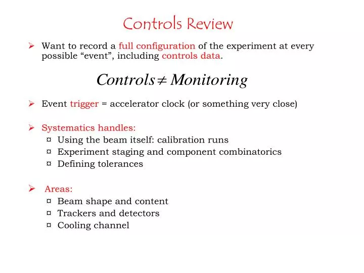
Controls Review. Want to record a full configuration of the experiment at every possible “event”, including controls data . Event trigger = accelerator clock (or something very close) Systematics handles: Using the beam itself: calibration runs

E N D
Controls Review • Want to record a full configuration of the experiment at every possible “event”, including controls data. • Event trigger = accelerator clock (or something very close) • Systematics handles: • Using the beam itself: calibration runs • Experiment staging and component combinatorics • Defining tolerances • Areas: • Beam shape and content • Trackers and detectors • Cooling channel
Assumptions • Stated Goal: eout/ein of 10 –3 • Assume there will be a standard (or agreed to) definition of 6-D cooling. • Assumethat the tracker can give us precision particle position and momemtum that this won’t contribute significantly to the error. • Assume particle ID < 1% error • The main sources of systematic errors are in the cooling channel and detector solenoids, which will need to be under control to a level such that up to 10 independent sources of systematics will be < 10-3 • Suggested goal to keep each source of error <3*10-4 level
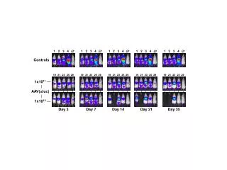
Quantity MICE organs Tolerance Monitor Beam measurement (suggested) Responsible Channel count Beam ISIS beam target magnets Collimators Diffuser… TBD Alignment with expt? Settings Beam instrumentation (profile & halo monitors ?) others Measure beam averages and correlations, composition and emittance With/without diffuser Drumm/Tilley Beam detectors TOF Cherenkov TBD Volts, currents Occupancies, Dead channels others Measure TOF vs nominal beam momentum Calibrate in configuration with electrons in beam ? Palladino/ Bonesini Summers Emittance tracker <<10-3 TBD Compare one tracker to the other with empty abs and no RF Bross/ Long PID 10-3 TBD Palladino/ Bonesini Gregoire Tortora DE/dX Hydrogen absorber A few 10-3 Temperature Pressure thickness Others Measure energy difference in configuration without RF and with full absorber(s) Zisman Wing Lau MACC Ishimoto DE RF system A few 10-3 Volts Phases Temps Measure energy of outgoing muons vs phase or with/without RF Zisman Derun Li optics positions of coils internal survey some mm ISIS alignement system position monitors? transfer matrix: (pt, pL, phi, x0 , y0)in <-> (pt, pL, phi, x0, y0)out measure with no RF and empty absorbers each time one changes the magnetic set-up. Green /Black currents few 10-4 amp-meter Zisman / Green mag field some 10-4 ~ mag probes temp probes Zisman/Green / Linde • Start-up systematics chart
Beamline Static = not expected to change with time (but may drift) Dynamic = changing with time ISIS proton beam trigger (pulse) and intensity (voltage level) (dynamic) ISIS proton beam loss monitors - ×few - voltage level, 20 ms cycles (dynamic) Target position (static) Target drive amplitude (dynamic) Target drive trigger (pulse) Beam Diagnostics: yet to be determined -Glasgow are looking at scintillators - X,Y beam profiles (N channels - dynamic) Settings of magnets (V, I) × 12 elements (static) = 9 quads, 2 dipoles, 1 sc-solenoid (static) Beam Line Vacuum (e.g. penning & pirani) Diffuser in place Vacuum state: = rough pump on/off = turbo pump on/off = valves open/closed (×2)
Particle ID – Cerenkov (2) - 8 analog channels for monitoring the (positive) HV's.- 8 analog channels for monitoring the analog responses of PM's to light pulses.- 1 digital output channel for triggering the light pulser - 8 TDC outputs (probably not important? depends on the noise levels).- 1 analog for oxygen sensor - 1 analog channel for monitoring the humidity inside the vessel. - 1 analog channel for a temperature probe- 1 analog channel for the He pressure inside the Cherenkov vessel. - 2 switches (over and underpressure)
PID – TOF(2) To measure t.o.f. with s ~ 70 ps, it is necessary to monitor detector status, environmental conditions (e.g., temperatures for signal cables) • HV setting ( ~ 80 channels) via CAEN SYS1527-SYS3527 mainframes • Temperature probes (~3) • Magnetic field probes (~3) • Additional (laser interlock, other.. ) Less than 100 channels to be under cold control system
PID - Calorimeter Now ~ 240 pairs