Download
1 / 16
160 likes | 299 Views
LEOS 2004. Optical Interconnection Networks: The OSMOSIS Project. Ronald Luijten, Wolfgang E. Denzel IBM Research, Zurich Research Laboratory, R ü schlikon, Switzerland Richard R. Grzybowski, Roe Hemenway Corning Incorporated, Science and Technology, Corning, NY, USA.

E N D
LEOS 2004 Optical Interconnection Networks:The OSMOSIS Project Ronald Luijten, Wolfgang E. DenzelIBM Research, Zurich Research Laboratory, Rüschlikon, Switzerland Richard R. Grzybowski, Roe HemenwayCorning Incorporated, Science and Technology, Corning, NY, USA
High Performance Computing Systems (HPCS) Illustrative HPCS example: IBM Blue Gene • Large distributed computing systems with 1000s of interconnected processor/memory nodes • Proliferating processor performance and parallelism (Teraflops) require interconnect performance to keep pace • Need for large-scale, high-bandwidth, low-latency packet switching interconnection network
X X X X X X X X X X X X HPCS Interconnection Networks Example of HPCS interconnection network Illustrative HPCS example: IBM Blue Gene • Must be able to switch short data packets reliably at high sustained rates with very low latency over arbitrary paths • Presently implemented as electronic packet switching networks,but quickly approaching electronic limits with further scaling • Future could be based on maturing all-optical packet switching,but need to solve the technical challenges and accelerate the cost reduction of all-optical packet switching for HPCS
OSMOSIS ProjectOptical Shared MemOry Supercomputer Interconnect System • Sponsored by US Dept. of Energy, NNSA, as part of the Accelerated Strategic Computing Initiative (ASCI) • Partners: Corning and IBM • Project duration: 2½ years (since Sep ‘03) • Objective: solving the technical challenges and accelerating the cost reduction of all-optical packet switches for HPCS interconnects by • building a full-function all-optical packet switch demonstrator system • showing the scalability, performance and cost pathsfor a potential commercial system
VOQs Com- biner Tx 2 Rx EQ 8x1 1x8 8x1 control WDM Mux Star Coupler control OpticalAmplifier 8x1 1x128 2 Rx EQ control OSMOSIS Demonstrator System - Overview All-optical Switch 64 Ingress Adapters 64 Egress Adapters 8 Broadcast Units 128 Select Units 1 1 1 Fast SOA 1x8 Fiber Selector Gates Fast SOA 1x8 Wavelength Selector Gates VOQs 1 Tx 128 8 control 64 64 control links central scheduler (bipartite graph matching algorithm) • 64-ports at 40 Gb/s port speed • Broadcast-and-select architecture • Combination of wavelength and space division multiplexing • fast switching based on SOAs
VOQs Com- biner Tx 2 Rx EQ 8x1 1x8 8x1 control WDM Mux Star Coupler control OpticalAmplifier 8x1 1x128 2 Rx EQ control OSMOSIS Demonstrator System - Adapters All-optical Switch 64 Ingress Adapters 64 Egress Adapters 8 Broadcast Units 128 Select Units 1 1 1 Fast SOA 1x8 Fiber Selector Gates Fast SOA 1x8 Wavelength Selector Gates VOQs 1 Tx 128 8 control 64 64 • Electronic Input Packet Buffers • virtual output queues (VOQ) • Optical Channel Transmitter • serialization & coding • electro-absorption modulator • DFB laser • Electronic control (Ingress) • buffer control & scheduling • control channel protocol • FPGA-based control links central scheduler (bipartite graph matching algorithm)
VOQs Com- biner Tx 2 Rx EQ 8x1 1x8 8x1 control WDM Mux Star Coupler control OpticalAmplifier 8x1 1x128 2 Rx EQ control OSMOSIS Demonstrator System - Adapters All-optical Switch 64 Ingress Adapters 64 Egress Adapters 8 Broadcast Units 128 Select Units 1 1 1 Fast SOA 1x8 Fiber Selector Gates Fast SOA 1x8 Wavelength Selector Gates VOQs 1 Tx 128 8 control 64 64 • Electronic Input Packet Buffers • virtual output queues (VOQ) • Optical Channel Transmitter • serialization & coding • electro-absorption modulator • DFB laser • Electronic control (Ingress) • buffer control & scheduling • control channel protocol • FPGA-based • 2 Optical Channel Receivers • high-speed PIN photodiodes • clock recovery (optimized for fast clock acquisition) • error correction • Electronic Output Packet Buffer • FIFO buffer • Electronic control (Egress) control links central scheduler (bipartite graph matching algorithm) ingress & egress side physically collocated
VOQs Com- biner Tx 2 Rx EQ 8x1 1x8 8x1 control WDM Mux Star Coupler control OpticalAmplifier 8x1 1x128 2 Rx EQ control OSMOSIS Demonstrator System – All-optical Switch All-optical Switch 64 Ingress Adapters 64 Egress Adapters 8 Broadcast Units 128 Select Units 1 1 1 Fast SOA 1x8 Fiber Selector Gates Fast SOA 1x8 Wavelength Selector Gates VOQs 1 Tx 128 8 control 64 64 • 8x1 WDM Multiplexer • PLC AWG • Optical Amplifier • EDFA with AGC • >20dBm output power • <7dB noise figure • 1x128 Star Coupler • 2-stage 1x8 / 1x16 • PLC splitters control links central scheduler (bipartite graph matching algorithm)
VOQs Com- biner Tx 2 Rx EQ 8x1 1x8 8x1 control WDM Mux Star Coupler control OpticalAmplifier 8x1 1x128 2 Rx EQ control OSMOSIS Demonstrator System – All-optical Switch All-optical Switch • Perfect Shuffle Interconnects 64 Ingress Adapters 64 Egress Adapters 8 Broadcast Units 128 Select Units 1 1 1 Fast SOA 1x8 Fiber Selector Gates Fast SOA 1x8 Wavelength Selector Gates VOQs 1 Tx • SOA 1x8 Fiber Selector GatesSOA 1x8 Wavelength Selector Gates • switching time <10 ns • extinction ratio >20 dB (dynamic) • gain >15 dB • polarization-dependent gain 0.45 dB (typical) • noise figure <6.5 dB • saturation power >17.5 dBm • low wavelength-dependent power variation • 8x1 Combiner • PLC combiner • 1x8 & 8x1 WDM Mux/Demux • Dual PLC AWG 128 8 control 64 64 • 8x1 WDM Multiplexer • PLC AWG • Optical Amplifier • EDFA with AGC • >20dBm output power • <7dB noise figure • 1x128 Star Coupler • 2-stage 1x8 / 1x16 • PLC splitters control links central scheduler (bipartite graph matching algorithm)
VOQs Com- biner Tx 2 Rx EQ 8x1 1x8 8x1 control WDM Mux Star Coupler control OpticalAmplifier 8x1 1x128 2 Rx EQ control OSMOSIS Demonstrator System – Central Control All-optical Switch 64 Ingress Adapters 64 Egress Adapters 8 Broadcast Units 128 Select Units 1 1 1 Fast SOA 1x8 Fiber Selector Gates Fast SOA 1x8 Wavelength Selector Gates VOQs 1 Tx 128 8 control 64 64 control links central scheduler (bipartite graph matching algorithm) • Central Scheduler • central clock and system synchronization over control links • central arbitration for entire fabric (FLPPR) • control channel protocol for adapter control links and switch command links • FPGA-based
VOQs Com- biner Tx 2 Rx EQ 8x1 1x8 8x1 control WDM Mux Star Coupler control OpticalAmplifier 8x1 1x128 2 Rx EQ control all-optical packet transfer 5 4b SOA switch command packet waiting 1 central arbitration (FLPPR) 3 request 2 grant 4a OSMOSIS Demonstrator System – Packet Scheduling All-optical Switch 64 Ingress Adapters 64 Egress Adapters 8 Broadcast Units 128 Select Units 1 1 1 Fast SOA 1x8 Fiber Selector Gates Fast SOA 1x8 Wavelength Selector Gates VOQs 1 Tx 128 8 control 64 64 control links central scheduler (bipartite graph matching algorithm)
Delay [packet cycles] with FIFOs with VOQs conventionalarbiter (PMM) 1 receiver with FLPPR 2 receivers k 1 0 50% 100% Throughput OSMOSIS Delay/Throughput Measures • Virtual output queues (VOQ) in ingress adapters avoid head-of-line blocking (i.e. throughput saturation around 58%) • Novel Fast Low-latency Parallel Pipe- lined ARbitration (FLPPR) implementation of heuristic iterative round-robin scheme keeps low-load latency low, while still allowing multiple iterations (k=6 for 64x64) • Dual receivers per output port improve delay at high loads(cost of >2 receivers not justified)
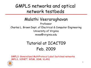
2048-port 2-level Fat Tree Topology 32 basicOSMOSIS modulesof size 64x64 ... ... ... X X X X 64 basicOSMOSIS modulesof size 64x64 X X X X X X X X .. .. .. .. .. .. .. ... ... ... ... ... ... ... ... 1 2048 OSMOSIS Multistage Scalability • Single-stage scalability to 1000s of ports is not feasible economically due to the square arbitration complexity and physical bulk of optical components • Scalability solution must be based on multistage topology involving • electronic buffers between stages • link-level flow control, routing and congestion control management • Wavelength scalability in the basic modules allows further growth without more stages
OSMOSIS Requirements Met • Low switching overhead (<25%) • dead time for SOA switching • preamble for synchronization • packet header • forward error correction (FEC) bits • Low bit-error rate (10-21), reliable delivery • raw error rate target <10-10 • with single-error FEC on header and data →10-17 • with multiple-error detection and retransmission →10-21 • Low latency / high throughput • low optical-path delay, fast SOA switching • fast encoding/decoding → code block size compromise • fast central scheduling through pipelined implementation • two receivers per egress port • virtual output queues (VOQ) • Scalability to 2048 nodes • 3-stage, 2-level Fat Tree topology
25ns Input waveform with intentional 3dB path dependent power variation is detected error free over three days without benefit of FEC OSMOSIS Project Status • Physical and control architecture definition, simulations • Initial lab demo of optical data path • Progressing on plan to deliver final demonstrator system • Engineering work required for commercially viable system,aiming at 1/100 part count by integration of functional OE devices to reduce cost, size and power consumption
Acknowledgements Other contributors: • Michael Sauer, Martin Hu and Heath Rasmussen at Corning • Ron Karfelt and the team at Photonic Controls, LLC • Cyriel Minkenberg, François Abel, Raj Krishnamurthy, Ilias Iliadis,Urs Bapst, Peter Mueller and Henry Brandt at IBM • Marco Galli and the team at g&o embedded systems gmbh