Download
1 / 44
440 likes | 546 Views
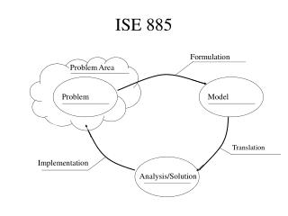
ISE 240. Introduction and Materials. What is Manufacturing?. Manu factus – “made by hand” Converting raw materials into products Making discrete or continuous products, equipment, machines, tools, assemblies… Production engineering Adding value to raw materials. Product Design

E N D
ISE 240 Introduction and Materials
What is Manufacturing? • Manu factus – “made by hand” • Converting raw materials into products • Making discrete or continuous products, equipment, machines, tools, assemblies… • Production engineering • Adding value to raw materials
Product Design Machines/Tooling Process Planning Materials Manufacturing Production Control Purchasing Shipping Support Services Marketing Sales Customer Service Manufacturing Activities
Material Classifications • Ferrous metals – carbon/alloy/stainless/tool & die steels • Nonferrous metals – Aluminum, copper, nickel, titanium, precious metals • Plastics (polymers) – thermoplastics, thermosets, elastomers • Ceramics, glasses, diamond, graphite, etc. • Composites and new materials with unique properties
Material Properties • Mechanical – strength, toughness, ductility, hardness, elasticity, fatigue, creep, ratios • Physical – density, specific heat, thermal expansion, thermal conductivity, melting point, magnetic and electrical qualities • Chemical – oxidation, corrosion, degradation, toxicity, flammability • Manufacturing – manufacturability, effects on product properties, service life, cost
Material Properties • The properties of materials determine the possible manufacturing processes that can be used to make products • The properties of materials are influenced by the manufacturing processes that are used to make products
Mechanical Properties of Various Materials at Room Temperature These are engineering properties of materials
Crystal Structure of Metals • Unit cell – the smallest group of atoms showing the characteristic lattice structure of a particular metal • Allotropism or Polymorphism – having more than one type of crystal structure • Anisotropy – when a single crystal has different properties when tested in different directions (like plywood)
Body Centered Cubic (bcc) Alpha iron, chromium, molybdenum, tantalum, tungsten, vanadium
Face Centered Cubic (fcc) Gamma iron, aluminum, copper, nickel, lead, silvver, gold, platinum
Hexagonal Close Packed (hcp) Beryllium, cadmium, cobalt, magnesium, alpha titanium, zinc, zirconium
Grain Boundaries and Size • High nucleation rate – large number of smaller grains per unit volume • High growth rate relative to nucleation – fewer grains, larger grain sizes • Rapid cooling produces smaller grains, whereas slow cooling produces larger grains
Plastic Deformation of Polycrystalline Metals When sheet metal is subjected to further forming operations, cracks form in the direction of rolling
Imperfections - Dislocations • Work/Strain Hardening • Entangled dislocations interfere with each other • Grain boundaries or impurities impede slip
Deformation • Elastic – returns to original shape when force is removed • Plastic – permanent deformation • Slip Plane – planes of atoms slip over each other due to shear stress • Twinning – a portion of the crystal abruptly forms a mirror image of itself across a plane • Shear stress = Applied Shearing Force / Cross Sectional Area • Slip Systems – slip planes in different directions – countable for different crystal structures • bcc – 48 – high probability that externally applied shear stress will act on a slip plane, but high stresses needed – materials have good strength and moderate ductility • fcc – 12 – moderate probability but low stresses needed – materials have moderate strength and good ductility • hcp – 3 – low probability but more slip systems become active at higher temperatures – materials are brittle at room temperature
(b) Material Behavior - Tension • Tension test – used to find mechanical properties such as strength, ductility, toughness, elastic modulus, and strain hardening • Typical gage length lo=50 cm, cross-sectional area Ao, and diameter 12.5 mm • The load applied and the extension of the specimen are measured during the test Figure 2.1 (a) A standard tensile-test specimen before and after pulling, showing original and final gage lengths. (b) A typical tensile-testing machine.
Engineering Stress-Strain Curve • Tensile specimens initially show elongation proportional to the load in the linear elastic behavior region • As load is increased above the yield stress, the specimen starts to plastically and permanently deform • 0.2% elongation point, or an offset of 0.002 strain helps identify Y for ductile materials • Necking occurs beyond the UTS or maximum engineering stress of the material • Eventually, fracture stress is reached Figure 2.2 A typical stress- strain curve obtained from a tension test, showing various features.
Definitions Engineering or nominal stress Engineering strain Volume constancy Elastic modulus (Young’s) = stress/strain in the elastic region Yield point or yield stress – elastic limit – permanent or plastic deformation begins. Quite difficult to determine so value quoted is most often a proof or offset stress, typically the 0.2% proof stress represents the yield stress. Ultimate tensile strength or tensile strength
Ductile Material Uniform deformation Neck begins to form – max. load Fracture Deformation concentrated in neck
Ductile Failure Copper Duralumin Ductile materials exhibit significant permanent deformation after yielding before fracture.
Brittle Materials Exhibit very little deformation after yielding and fracture immediately
Measures of Ductility Percent elongation Percent reduction in area Toughness = area under the stress/strain curve For ductile materials these measures are quite high. For brittle materials these measures are close to zero To produce a new shape by a mechanical deformation process the material must be ductile otherwise fracture occurs Chalk has zero ductility because it does not stretch or reduce in cross sectional area, where as clay does
Loading and Unloading of Tensile-Test Specimen For the second loading the yield point is greater than before. i.e. higher stresses are need to cause further permanent deformation. This phenomenon is known as work hardening and means that materials that have been previously cold worked are more difficult to deform and behave in a more brittle way. Heat treatment called annealing is required to restore the previous material properties Figure 2.3 Schematic illustration of the loading and the unloading of a tensile- test specimen. Note that, during unloading, the curve follows a path parallel to the original elastic slope.
True Stress and Strain • Engineering stress is based on the original cross sectional area Ao rather than the instantaneous area • For small values of strain, engineering and true strains are approximately equal Since the cross sectional area is always reducing then True stress is always greater than true strain. True strain is always less than engineering strain and the difference increases with increased strain.
True Stress and Strain vs Engineering/Nominal/Apparent Stress and Strain Figure 2.5 (a) Load-elongation curve in tension testing of a stainless steel specimen. (b) Engineering stress-engineering strain curve, drawn from the data in Fig. 2.5a. (c) True stress-true strain curve, drawn from the data in Fig. 2.5b. Note that this curve has a positive slope, indicating that the material is becoming stronger as it is strained. (d) True stress-true strain curve plotted on log-log paper and based on the corrected curve in Fig. 2.5c. The correction is due to the triaxial state of stress that exists in the necked region of a specimen. K = strength coefficient n = work-hardening exponent Toughness = area under the true stress-true strain curve
Strain Hardening Index True strain at which neck forms
Tension and Compression Figure 2.19 Schematic illustration of types of failures in materials: (a) necking and fracture of ductile materials; (b) Buckling of ductile materials under a compressive load; (c) fracture of brittle materials in compression; (d) cracking on the barreled surface of ductile materials in compression. Figure 2.20 Schematic illustration of the types of fracture in tension: (a) brittle fracture in polycrystalline metals; (b) shear fracture in ductile single crystals--see also Fig. 1.6a; (c) ductile cup-and-cone fracture in polycrystalline metals; (d) complete ductile fracture in polycrystalline metals, with 100% reduction of area.
Compression and Torsion Tests Figure 2.9 Disk test on a brittle material, showing the direction of loading and the fracture path. Figure 2.10 Typical torsion-test specimen; it is mounted between the two heads of a testing machine and twisted. Note the shear deformation of an element in the reduced section of the specimen.
Effects on Temperature on Material Properties • Increasing temperature: • Raises ductility and toughness • Lowers yield stress and modulus of elasticity • Can cause problems with oxidation • May reduce accuracy of finished products • Increases costs due to energy input required to raise temperatures Figure 2.7 Typical effects of temperature on stress-strain curves. Note that temperature affects the modulus of elasticity, the yield stress, the ultimate tensile strength, and the toughness (area under the curve) of materials.
Recrystallization and Annealing Annealing is a heat treatment process in which the temperature of previously cold worked material is raised above the recrystallization temperature and allowed to cool slowly. A new grain structure is formed with lower strength and increased ductility
Recrystallization Temperatures Metals are in the recrystallization range if temperatures are raised above half of the melting point on the absolute temperature scale
Hot Working Conditions • If metal working is carried out above the recrystallization temperature these are called hot working conditions • Strain hardening and recrystallization take place at the same time so deformation is easier and ductility is improved • Hot working conditions are defined as temperatures above half the melting point on the absolute scale (text book uses 0.6 of melting point • Cold working is below 0.3 of melting point and warm working is the intermediate range between 0.3 and 0.5 of melting point.
Homologous Temperature Scale Temperature scale between 0 and 1, where 1 corresponds to the melting point of the metal in degrees absolute. This enables hot, warm and cold working conditions to be defined for all metals.
Hardness Tests Figure 2.12 General characteristics of hardness-testing methods and formulas for calculating hardness. The quantity P is the load applied. Source: H. W. Hayden, et al., The Structure and Properties of Materials, Vol. III (John Wiley & Sons, 1965).
Hardness Conversion Chart Figure 2.14 Chart for converting various hardness scales. Note the limited range of most scales. Because of the many factors involved, these conversions are approximate. Brittle materials generally have increased hardness. UTS for steels is approximately proportional to hardness for steels.
Impact Test Charpy test Izod test Energy absorbed in breaking the specimen is a measure of the impact strength. Brittle materials break more easily than ductile materials
Fatigue and S-N Curves Figure 2.15 Typical S-N curves for two metals. Note that, unlike steel, aluminum does not have an endurance limit. Fatigue Strength can be improved by inducing compressive residual stresses on surfaces (i.e., shot peening); surface or case hardening, providing a fine surface finish to reduce the effects of imperfections, or selecting appropriate materials with specified quality standards. Fatigue Strength can be decreased by tensile residual stresses, decarburization, surface pits (corrosion), hydrogen embrittlement, galvanization, and electroplating.
Fatigue Testing Fatigue Failure Fatigue is failure that results from the repeated application of what may be relatively light stresses repeatedly over many cycles. Fatigue resistance is important for applications in which stresses are applied repeatedly, e.g. rotating shafts, pressure vessels, aircraft structures, etc.
Creep and Creep Testing Creep is permanent deformation results from constant loads (stresses) applied over long periods. These loads are usually less than those that would normally cause yielding of the material. Creep increases with elevated temperatures Typical creep curve
Creep and Creep Testing Creep is important in applications where constant stresses are applied over long periods, particularly at elevated temperatures. Examples are gas turbine blades, plastic water pipes, pressure vessels, etc. Creep resistant materials can be developed. Grain boundaries contribute to creep, particularly those perpendicular to the direction of loading. This has led to special casting techniques to produce single crystal turbine blades.
Residual Stresses • Stresses that are locked up in the product after processing due localized deformation or heating. • Machining and surface processing • Bending stresses • Welded fabrications, etc. • Can result in unwanted distortion, stress-corrosion failure in service, reduced fatigue life, etc.