Download
1 / 56
560 likes | 709 Views
Outline. Introduction Tasks achieved in GP I Earthquake load Alternative # 2 Design of compression & zero force members Design of tension members Design of end beams & columns Design of welded connection Design of bolted connection Material cost Comparison and final design

E N D
Outline • Introduction • Tasks achieved in GP I • Earthquake load • Alternative # 2 • Design of compression & zero force members • Design of tension members • Design of end beams & columns • Design of welded connection • Design of bolted connection • Material cost • Comparison and final design • Conclusion
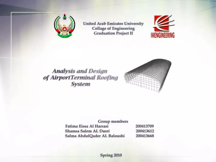
Introduction • Currently, Al Ain International Airport is under extension work due to: • Growth in the passenger flights • Increase in the airline traffic to Al Ain • Our graduation project was motivated by the ongoing expansion of Al Ain International Airport. • The roofing system of a typical airport’s terminal was selected, analyzed and then designed.
Objective • The major objective was to utilize the theory of structures principals and the Load and Resistance Factor Design concepts to; • Model • Analyze • Design the steel elements and connections forming the main supporting element of the long-span roofing system.
GP I Summary • Comprehensive literature review was conducted on common construction material, structural systems, and dimensions of existing or proposed airport terminals. • Two alternative architectural designs were selected. • A general structural layout was generated using the AutoCAD software to describe all the components of the first alternative system.
GP I Summary • The initial computer model was developed for the first alternative system using the structural analysis software SAP2000. • The various design loads acting on the first alternative system including dead loads, roof live loads and wind loads were calculated based on the latest American standards developed by the American Society of Civil Engineers (ASCE7-05). • A detailed 3D model was developed using SAP2000 to simulate the behavior and response of the selected structural system under the computed loads.
Generation of the Alternatives First Alternative: Multi-Curvature Arch
Generation of the Alternatives • Second Alternative: Traditional Single-Curvature Arch
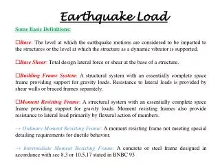
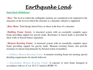
Earthquake Load An earthquake is a shake of the earth's surface usually occurred by the release of underground stress along fault lines. This release causes movement in masses of rock and resulting seismic waves.
Earthquake Load • Earthquake Load • Severe Lateral load • Very complex & uncertain • Potentially more damaging than wind loads
Earthquake Load • Earthquake Load • Designing buildings to resist earthquakes requires that ground motions be translated into forces acting upon a building. Earthquake forces are called lateral forces. • The magnitude of earthquake load depends on the mass of the structure and on the horizontal acceleration imparted from the ground shaking.
Earthquake Load Calculations Case # 1 Case # 2
Earthquake Load Calculations The procedure of calculating the earthquake load acting on the building structure is in accordance with ASCE7-05/IBC 2009 standards. • Required values, factors and coefficients :
Seismic activity in UAE (MCE) Dubai Ss Values: Abu Dhabi = 0.6 Dubai = 0.83 Al Ain = 0.675 Abu Dhabi Al Ain
Seismic activity in UAE (MCE) S1Values: Abu Dhabi = 0.24 Dubai = 0.33 Al Ain = 0.27 Dubai Abu Dhabi Al Ain
Seismic activity in UAE Long - Period Transition Period : TL = 8
Earthquake Load Calculations • Base Shear (Vb) ; the total lateral load caused by the earthquake at the base of the structure. • Vb= Cs W • Where • Vb; the seismic base shear. • W ; the effective seismic weight “the total dead load of the entire building”. • Cs ; the seismic response coefficient
Earthquake Load Calculations • The lateral seismic force (Fxf) ; • Fxf = Cvfx V b • The calculated base shear is distributed among all floors with respect to: • the heights of the building • their effective weight • Vertical distribution factor (Cvxf ) ; • Cvfx=( Wxfhxfk /Σi=1 nWi hik )(Cthnx)
Case #1 Case #2 • Alternative # 2 Results • Results
Dead Load Calculations • The various design loads calculations were performed based on [ASCE/SEI 7-05]. • Results
Live Load Calculations • Live load acting on a typical truss joint: • Results
Direction #1: Perpendicular to 204 m Direction #2: Perpendicular to 118.5m • Wind Loads Calculations • The main equation • In wind load calculations, it is important to divide the system itself to different sections.
Wind Loads Calculations Wind direction • Results
Computer Model • The design of the airport roofing system using AutoCAD software 4 m The different joints and elements were labeled in an Excel spreadsheet to be used as an input in SAP2000 Software 31 m 118.5 m System’s Material Steel (A572-G50) Roofing System Type Space Truss
Computer Model Horizontal Structural Elements Beams & Columns Supports (Hinges)
Assigning Structural Loads in SAP2000 • To simulate the behavior and response of the structural system under the computed loads . • To conduct full structural analysis of the entire system. Assignment of the dead load Assignment of the live load
Assigning Structural Loads in SAP2000 Assignment of the wind load Assignment of the earthquake load
Analysis Stage The analysis was carried out according to 11 loads combinations • 1.2D +1.6L • 1.2D + 1.6W + 0.5L • 1.2D + 1E + 0.5L Truss 24 Truss 3 Steel Section Circular cross-section
SAP 2000 Output Table : SampleSAP2000 Output
Final Design Process • The major objective of this phase is to insure the safety and economy of the system by comparing the element's resistance with the applied load. • A comparison was done between the two units based on the tension and compression forces for each of the combination.
Final Design Process • Based on the type of load, the structural elements were classified as: • Zero force members • Compression members • Tension members • Design of Zero-Force Members Zero-force members are special members that are designed to satisfy stiffness criterion only (i.e.; strength is not an issue). These members should be designed following stiffness requirement of compression members.
Design of Compression Members • Steel is known to be sensitive to buckling and, therefore, special attention should be given to buckling behavior of these elements. • Procedure of designing the compression members Data obtained from LRFD manual
Design of Tension Members • Tension members are structural elements that are subjected to axial tensile forces. Failure mode #1 Design of steel due to yielding in the gross section. Failure mode #2 Design of steel due to tensile rupture in net sections
Specifications and Final Design After designing the different elements, the appropriate steel section was selected for each element.
Alternative #1 Steel sections Alternative #2 The design of the first upper cord is identical to the second one and same for the diagonals.
Design of end beams and columns • End columns and beams are secondary elements that are intended to withstand self weight of cladding sheets. • They should be able to provide adequate strength for moments resulting from wind loads. Alternative #1
Connections • Steel members are usually connected in the fabrication shop by welding. • In the construction site either welding or bolting could be used; however, bolting is more recommended for quality control, ease and safety reasons.
Connections • There is a practical limit on the maximum length of steel members that could be carry to the construction site and that is about 12 to 14 meters Alternative #1 Alternative #2
Welded Connections Welding process; The elements are heated and fused with molten metal added to the joint The most commonly used welding techniques are : (1) Shielded Metal Arc Welding (SMAW), used for field welds. (2) Submerged Arc Welding (SAW), used for shop welds. The SAW process provides more penetration into the base metal and higher strength than the SMAW process. Type of Weld: Fillet Welds Fillet Welds (about 80% of all welds), those welds placed in a corner formed by two parts in contact (the parts to be welded)
Welded Connections • Type of Weld: Fillet Welds • About 80% of all welds, those welds placed in a corner formed by two parts in contact (the parts to be welded) • Types of length weld; • Longitudinal Welds • (Welds that are perpendicular to direction of the load applied) • Transverse Welds • (Welds that are parallel to the direction of the applied load)
Welded Connections • The procedure for designing Welded connections ∅Rn/in = 0.75(0.6 FEXX) (te) (1.5) Lw= Pu/(∅Rn/in) Lw,min = 4Sw Lw,max = 100Sw
Bolted Connections • Connections for tension members, such as truss members, are classified as concentric shear connections, since the centroid of the connector group (fasteners or bolts) coincides with the centroid of the member. Concentric connections
Bolted Connections • Two main load transfer mechanisms control such connections: • Bearing-Type Connections: • Transfer of loads depends on the Bearing at bolt holes. • The most commonly used bolts are A325 and A490 • 2. Friction-Type (Slip-Critical) Connections: • Load transfer depends on the friction between • connected parts.
Bolted Connections • The procedure for designing bolted connections ØRn/bolt = 0.75 Ab Ft Nb = Pu /(ØRn/bolt) S = π D / Nb Smin = 0.67d Smax = the smaller of [24t , 12]
Cost Estimation • To calculate the overall cost of the project, the weight of the overall structural elements must be calculated. • The truss is divided to; • Lower cord elements • Upper cord elements • Diagonals • Upper diagonals and • Horizontal elements • Purlins Horizontal elements (AL#2) Data obtained from LRFD manual