Download
1 / 25
250 likes | 367 Views
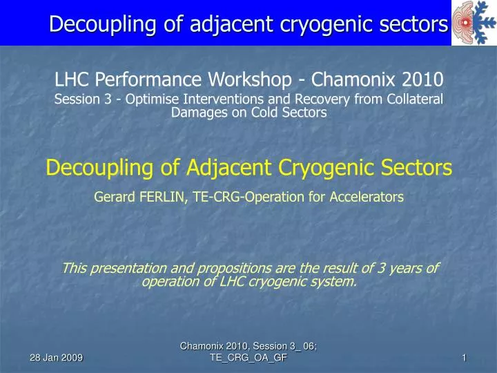
LHC Performance Workshop - Chamonix 2010 Session 3 - Optimise Interventions and Recovery from Collateral Damages on Cold Sectors Decoupling of Adjacent Cryogenic Sectors Gerard FERLIN, TE-CRG-Operation for Accelerators

E N D
LHC Performance Workshop - Chamonix 2010 Session 3 - Optimise Interventions and Recovery from Collateral Damages on Cold Sectors Decoupling of Adjacent Cryogenic Sectors Gerard FERLIN, TE-CRG-Operation for Accelerators This presentation and propositions are the result of 3 years of operation of LHC cryogenic system. Chamonix 2010, Session 3_ 06; TE_CRG_OA_GF
Abstract The LHC sectors are coupled two by two via interconnection boxes allowing cryoplant cooling redundancy and efficient stand-by or low-beam-intensity operation. The present LHC cryogenic sectorization allows to performed mechanical interventions on the magnet cold-mass circuit of a sector, like diode or interconnection splice repairs while the adjacent sector remain in nominal cryogenic operation. However this sectorization does not allow exchanging a magnet or a QRL service module in a sector while keeping the adjacent sector in nominal cryogenic operation and the cooling redundancy ability. This presentation will describe, based on different scenarios, hardware update proposals allowing a complete separation of the two adjacent sectors. Chamonix 2010, Session 3_ 06; TE_CRG_OA_GF
Contents Actual configuration Running configuration Intervention on sector Scenarios proposed for intervention -One sector cooled by “normal” cryoplants, One sector under intervention. -One sector cooled by “redundant” cryoplants, one sector under intervention. • Summary Chamonix 2010, Session 3_ 06; TE_CRG_OA_GF
Courtesy L.Tavian Chamonix 2010, Session 3_ 06; TE_CRG_OA_GF
Actual running configuration Nominal scheme Each sector coupled with corresponding cryoplant. Chamonix 2010, Session 3_ 06; TE_CRG_OA_GF
Nominal scheme 1.8K unit 1.8K unit Chamonix 2010, Session 3_ 06; TE_CRG_OA_GF
Actual running configuration Low-intensity beam or stand-by scheme or • Cryoplant major failure redundancy scheme Two sectors coupled with one cryoplant. Chamonix 2010, Session 3_ 06; TE_CRG_OA_GF
Low-intensity or stand-by scheme 1.8K unit 1.8K unit Chamonix 2010, Session 3_ 06; TE_CRG_OA_GF
Contents Actual configuration Running configuration Intervention on sector Scenarios proposed for intervention -One sector cooled by “normal” cryoplants, One sector under intervention. -One sector cooled by “redundant” cryoplants, one sector under intervention. • Summary Chamonix 2010, Session 3_ 06; TE_CRG_OA_GF
Overall configuration during intervention on one sector Safety The sector must be “consigned” from pressure and gas flow. Cryo operation Cold valves must be protected from air and moisture condensation/ice. Configuration adopted for each affected circuit Two valves locally consigned with helium gas buffer in between at room temperature and 1 bar (pressure monitored) Chamonix 2010, Session 3_ 06; TE_CRG_OA_GF
Present status temporary tool 28 Jan 2009 Chamonix 2010, Session 3_ 06; TE_CRG_OA_GF 11
Present status during magnet exchange. Circuits C (LHe 4.5K), D (Return GHe 20K), E (Magnet thermal screen 70 K), F (QRL thermal screen 85 K) are protected by GHe buffer, but protection for Header B (GHe pumping line, 15 mbar, 4K) improvable. Exchanging a magnet or a QRL service module in a sector while keeping the adjacent sector in nominal cryogenic operation is not possible without important risk! 28 Jan 2009 Chamonix 2010, Session 3_ 06; TE_CRG_OA_GF 12
Contents Actual configuration Running configuration Intervention on sector Scenarios proposed for intervention -One sector cooled by “normal” cryoplants, One sector under intervention. -One sector cooled by “redundant” cryoplants, one sector under intervention. • Summary Chamonix 2010, Session 3_ 06; TE_CRG_OA_GF
QRL Header , 1 bar, air and moisture condensation/icing not controlled Chamonix 2010, Session 3_ 06; TE_CRG_OA_GF
Courtesy G. Riddone, N. Veillet, 2006 Chamonix 2010, Session 3_ 06; TE_CRG_OA_GF
Add DN250 valve on header B To be done Validation of design for the 5 valve boxes. In particular free space in QUI, point 18 and point 2 needs to be carefully checked. Impact on proximity piping & safety valves to be checked. Cost estimation (design, materiel, installation, pressure and X-ray tests): from 120 to 150 kCHF/sector Duration: 3 to 4 weeks. 28 Jan 2009 Chamonix 2010, Session 3_ 06; TE_CRG_OA_GF 17
Add DN250 valve on header B Pros: -Gas flow safety guaranteed during mechanical intervention. -Air and moisture condensation/icing prevented. -Warm up and de-icing of the cold compressor inlet filter much more easier. -Restore possibility of leak-tight insulation between header B and QURC (repair inlet valve, Cold Compressor exchange…) Cons: -Possible only with the two sectors at room temperature. -Time schedule impact. 28 Jan 2009 Chamonix 2010, Session 3_ 06; TE_CRG_OA_GF 18
Contents Actual configuration Running configuration Intervention on sector Scenarios proposed for intervention -One sector cooled by “normal” cryoplants, One sector under intervention. -One sector cooled by “redundant” cryoplants, one sector under intervention. • Summary Chamonix 2010, Session 3_ 06; TE_CRG_OA_GF
Add a new valve-box on QRL junction region Chamonix 2010, Session 3_ 06; TE_CRG_OA_GF
Example Sector 8-1 Chamonix 2010, Session 3_ 06; TE_CRG_OA_GF
Add new valve box on junction region with 6 cryo-valves To be done Validation of design for the 8 junction region. Impact on proximity piping & safety valves to be checked. Cost estimation (design, materiel, installation, pressure and X-ray tests): from 300 to 350 kCHF/sector Impact on LHC time schedule: 4 to 6 weeks. 28 Jan 2009 Chamonix 2010, Session 3_ 06; TE_CRG_OA_GF 22
Add new valve box on junction region with 6 cryo-valves Pros: -Same than previous solution plus -Redundancy of cryoplant guaranteed Cons: -Integration design to be checked and validated. -Possible only with the two sectors at room temperature. -Cost (time schedule and money) 28 Jan 2009 Chamonix 2010, Session 3_ 06; TE_CRG_OA_GF 23
Other points not detailed HRL valves to be remotely driven WRL by pass in QUI area QUI purge panel to be separate in two half parts (one part/sector). … 28 Jan 2009 Chamonix 2010, Session 3_ 06; TE_CRG_OA_GF 24
Summary • Heavy intervention (exchanging a magnet or a QRL service module) while keeping the adjacent sector in nominal cryogenic operation will be possible only by upgrading the gas buffer system on header B. To restore possibility of leak-tight insulation between header B and Cold Compressor unit, a new valve is needed. • If the cryoplant redundancy is mandatory during the magnet exchange, a valve box must be added on the junction region. Thank you Chamonix 2010, Session 3_ 06; TE_CRG_OA_GF