Download
1 / 122
1.44k likes | 2.35k Views
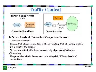
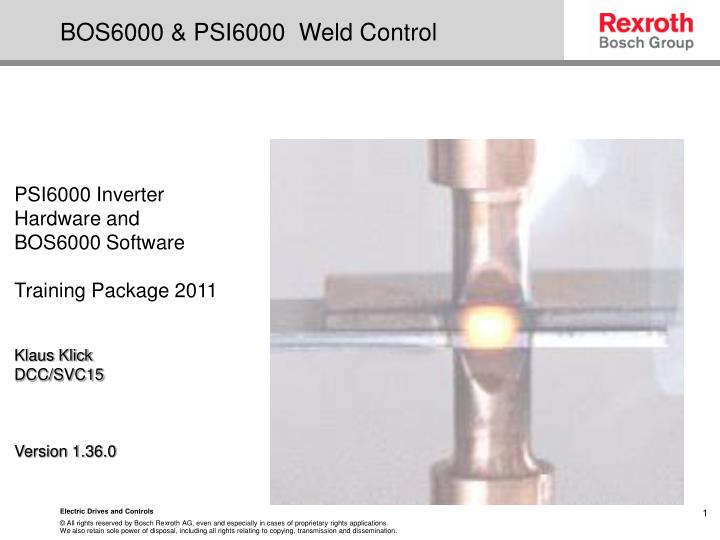
BOS6000 & PSI6000 Weld Control. PSI6000 Inverter Hardware and BOS6000 Software Training Package 2011 Klaus Klick DCC/SVC15 Version 1.36.0. Contents P age 1. System overview Pg 7 Welding Sequence Pg 10 Hardware configuration Pg 13 Timer standard configuration Pg 15

E N D
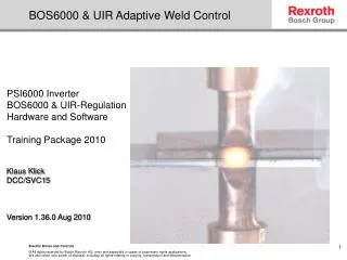
BOS6000 & PSI6000 Weld Control PSI6000 Inverter Hardware and BOS6000Software Training Package 2011 Klaus Klick DCC/SVC15 Version 1.36.0 Electric Drives and Controls
ContentsPage 1 System overview Pg 7 Welding Sequence Pg 10 Hardware configurationPg 13 Timer standard configuration Pg 15 Timer Name & I/O configuration Pg 17 Software communication Pg 22 Ethernet configuration Pg 23 BOS 6000 Software Pg 25 Programming page Pg 29 Icons Pg 30 Welding Sequence Pg 31 Programming exercise Pg 35 Copy Parameter Pg 36 Copy Programs / Timer Pg 37 Current Monitoring Pg 46 Extended Welding Sequence / Pressure Profile Pg 52 Electric Drives and Controls
Contents Page 2 Heat Stepper Pg 53 Heat Stepper & Tip dressing Pg 55 General set-up Pg 56 Electrode set-up Pg 58 Power Unit set-up Pg 62 I/O Diagnosis Pg 63 Simulate Start Pg 66 Timer Information Pg 67 Last Weld Pg 68 Plant Layout Pg 69 Log In / Compare Pg 72 Protocols Pg 76 Overview Pg 80 Error Table Pg 81 Pre-Warning F2 Pg 83 Correction Pg 87 Electric Drives and Controls
Contents Page 3 Force Calibration Pg 89 Current Calibration Pg 96 Set Up Heat Stepper Curves Pg 106 Set Up Tip Dresser Curves Pg 107 Backup Pg 108 Restore Pg 111 Help Page F1 Pg 116 How to extract spatter data Pg 118 Electric Drives and Controls
BOS6000 & PSI6000 Weld Control System Overview Electric Drives and Controls
Mains Input Rectification DC-Link Inverter 1 kHz Current-Feedback Voltage-Feedback Welding Gun Welding Equipment Machine Interface, I/O Bussystem Pressure / Force (0 -10VDC) 24 VDC Supply / Stop Circuit Optional Voltage-Feedback Current-Feedback Welding Gun Electric Drives and Controls
Overview PSI6000 Inverter and Transformer Primary sensors for KSR Inverter output 500V 1000Hz to the Gun Secondary coil (KSR) UIR Connections Typical ouput 5-12v DC 4 – 120kA, 1000Hz depending on Transformer Configuration. Electric Drives and Controls
Welding Sequence F = Force [kN]I = Current [kA]t = time [ms] Gun close open Weld Current SQZ WLD HLD Squeeze time Weld time Hold time Electric Drives and Controls
Material-resistance 1 Material-resistance 2 Resistance Welding Process Basics Electrode 1 Contact-resistance Electrode-Sheet1 Sheet 1 Contact-resistance Sheet-Sheet Sheet 2 Contact-resistance Electrode-Sheet2 Electrode 2 Electrode-Force F [kN] Q = R x I² x t Current I [kA] Electric Drives and Controls
BOS6000 & PSI6000 Weld Control Hardware Familiarisation Electric Drives and Controls
Bosch Rexroth Welding Control Panel Device Familiarisation typical setup 4.) Signal lamps 5.) Main Switch 7.) 2x PST6250.333L1 8.) 2x Main Switch 9.) Fuses Electric Drives and Controls
Bosch Rexroth Welding Control Panel Device Familiarisation typical setup Roboter bus system (here: optical Interbus) Bosch Rexroth Welding Control (timer) Main switch including FI Electric Drives and Controls
Timer Standard Configuration I/O Card slot Adaptive control slot Field bus module slot Side View Electric Drives and Controls
Understanding Weld Timer Type Codes Welding controls PSI6300.100L1 PSI6300.333L1 PSI6300.350L1 PSI6300.773L1 PSI63C0.357L1 PSI63S1.259L1 Transformers PSG6130 Electric Drives and Controls
Timer Configuration PSI 6100.201L1 Profibus I/O Serial Com Parallel I/O 24 Volts internal / external supply, see next page. External pressure control to prop valve Secondary current feedback, Transformer temp feedback. Output to the transformer Electric Drives and Controls
24volts Distribution Internal links Electric Drives and Controls
External Fan Operation The fans are normally located at the rear of the panel, forcing air to be driven across the fins of the heat sink. Electric Drives and Controls
Proportional Valve Control and feedback +24volt feedback, from the prop valve, tells the welding control that the demanded pressure has been reached, this then allows robot control to give the command to close the gun and allow the weld schedule to commence. If no prop valve is used, then +24volts and 0volts must be supplied to pin 4 & 2 !! Electric Drives and Controls
Transformer Feedback Industry Standard is 150mV / kA. This is adjusted automatically during a calibration procedure to suit the individual application A normally closed contact in the transformer, feeds back temperature OK. If no feedback is available, then these pins must be shorted. Electric Drives and Controls
Software Communication Wiring schedule for the Serial port Software Communication is normally via a specific communications card, via Interbus / Ethernet…etc. You can also connect directly to individual timers via the serial port, X1 Electric Drives and Controls
Ethernet Communication configuration When connecting via an Ethernet link, please ensure you have set the I.P address correctly on the computer, otherwise no communication will be possible. This indicates that your computer has detected a local area connection. To access the IP setting, double click the icon, with your mouse. If you do not have this icon present, select the option below Electric Drives and Controls
Ethernet Communication Configuration The General tab will now become visible A further configuration screen will appear Ensure that the IP address you select does not exactly match the IP address of the Timer, the last digit should be different Select Properties Select Internet Protocol (TCP/IP) then OK Setting the IP Address Enter an IP Address and subnet mask then OK Select, Use the following IP Address then OK Electric Drives and Controls
BOS6000 BOS6000 Software Familiarisation Electric Drives and Controls
BOS6000 Username & Password Electric Drives and Controls
Timer Reference 2. Add the timer name 3. Add any reference comment 4. Select your communication method. V24, Ethernet….etc 5. If you are connecting via Ethernet, then insert the IP address here 6. Select Online or Offline mode 7. Select protocol to enable the UIR monitoring 8. Select the direction of data flow, on initial communication 1.To add a new or additional timer, select the Add button first, the Add/change Timer box will then appear above 9. When the information has been installed, press OK 10. Select continue button to access the program data Electric Drives and Controls
Timer Status Monitor the Status and Description window, if a red bar appears and stays then there is a problem with your communication path, cable, or the timer may be switched off. Monitor the Status and Description window, a yellow bar should proceed a green bar. This indicates that communication path is operational, and the database is being populated with the timer information. Please be patient, on the initial start-up it can take several minutes to gather all the data for the database. All subsequent connections will only take seconds to get on-line Electric Drives and Controls
Programming Program Page The spot number, program and communication status is found at the top of program page, as well as the drop down menu’s The raised tab indicates the page that is currently being viewed Nearly all functions/pages can be quickly accessed via the “icons” that are situated at the top of the pages. A single click will select the required page, and another single click will return you to your previous screen. Electric Drives and Controls
BOS6000 Icons Plant layout Error Table Protocols Compare Pre-warning Table Parameter Overview, for incorrect parameters Login Spot referenceComments Rights Administration Timer reference Overview Spot referenceTable Program Page (Parameter data) Correction Diagnosis(i/o interface) Set-up Electric Drives and Controls
Sequence The BOS6000 software only shows tabs, which are available.e.g: PSQ-Tab isonly shown, if XQR PCBis mounted in the timer. The BOS6000 software only shows parameter, which are accessible.e.g: COOL 2 time is only shown, if the number of impulses is bigger than 1. Monitoring parameters are only shown, if kA-monitoring is “ON” Electric Drives and Controls
Programming Program tabs By selecting individual tabs within the pages you can navigate around the software at the click of a button Dependent on the timer status, you can see if the timer is online, or offline. Blue is working offline Green is working online You can also see at a glance if the weld has a pre-heat, a post heat, or even if upslope or down slope. Electric Drives and Controls
Programming Sequence The sequence screen allows the user to see the programmed weld parameters at a glance Program Timer Pressure Weld time Weld current Hold Squeeze For PSI6000 inverters the times are all programmed in milliseconds. PST6000 timers are programmed in cycles 1 cycle = 20ms Electric Drives and Controls
Sequence To select a weld program:- to access the required program, simply select the program from the up/down buttons, or type in the actual program number. The electrode number will update when a program is selected. To select a spot number:- utilising the down arrow select the required spot number, and the program that is associated with it will automatically appear Inhibit Seq (P) (Inhibit this program sequence) This needs to be set to “Off”, if not then the weld sequence will be inhibited for this program only • Sequence:- There are 3 sequence options, Single: 1 weld sequence per start signal • Repeat: 1 weld sequence repeated until the start signal is dropped • Seam: 1 weld permanently on till the start signal is dropped Weld On/Off Int (P)(Internal weld on/off) This needs to be set to “On”, if not then the weld will be turned Off for this program only Electric Drives and Controls
Programming exercise • Please enter the following Weld programs • Step1: Prog1 – 2 • Step2: Prog3 – 5 Electric Drives and Controls
Programming exercise Copy1 If you select one Parameter, 2) You may copy this parameter Using the rightmouse button 1) You see the input range of this parameter Electric Drives and Controls
Programming exercise Copy2 Using the Copy feature from the main menue, you have all Options to copy any data from the weld timers. Electric Drives and Controls
Sequence Regulation:- Mix or Standard If Mix is selected, weld 1 & weld 3 can be programmed in PHA (phase angle) or KSR (constant current) mode If Standard is selected then weld 1 and weld 3 can only be programmed in the same mode as weld 2 Electric Drives and Controls
Sequence • *see illustration on the next sheet • Monitoring:Mix or Standard • Standard mode: the actual current is determined by the complete weld cycle including any cool times • Mix mode: the actual current is determined by the individual weld times Electric Drives and Controls
Sequence Electric Drives and Controls
Sequence • Programmed in scale units %,the greater the %Ht, then the greater %age of current flowing PHA: Phase Angle Regulation Phase angle, fixed value determined by program Half-cycle of mains voltage 31° 130 ° - Electrical degrees 0° 180 ° 120 99 0 -15 - Scale units (%) High current Programmable range Low current Electric Drives and Controls
Principle of Unregulated Phase angle welding Electric Drives and Controls
Principle of Constant current regulation Electric Drives and Controls
Sequence Electrode: 0 – 31 different electrodes can be selected, dependent on your firmware version Reweld: If this function is activated and a low weld current occurs with the start signal still high, the control will automatically attempt to reweld the program, if the weld is low again a weld fault is output. Note:- if there is no current, then a reweld will not be activated Electric Drives and Controls
Sequence Impulse: This function indicates how many times the weld 2, cool 2 function is repeated during one weld sequence. If the impulse function has a figure greater than 1, then the portion of the program that is inside the green shape is repeated however many times is programmed Electric Drives and Controls
Sequence Current monitoring • Current monitoring: • When the monitoring is activated (ON), the reference current and all the tolerance band parameters become visible Electric Drives and Controls
Sequence 1 Repeat factor, is the number of consecutive welds allowed in the conditional permissible tolerance band; if this occurs, the actual figure is displayed here 2 3 4 1 2 3 4 Electric Drives and Controls
Sequence Ref, kA is the programmed reference current Act. Ref. kA is the actual current achieved Average PHA is the actual Phase angle required to achieve the required current Electric Drives and Controls
Spot table In the spot reference table a particular spot name is linked to a program number and a timer.This allows selection of spots by their individual name. Important: The Spot reference table must be transferred into the timer to get active!! 1.) 3.) 2.) Electric Drives and Controls
4.) Spot table Electric Drives and Controls
Sequence If this Icon is coloured, then when pressed, the comments sheet for the actual spot number that is assigned to this program will be displayed The number of comment fields can be altered in the Config tool Electric Drives and Controls
Extended Sequence from this page the pressure profile function can be activated. When the profile is activated the force can be programmed to a specific value at any time during the weld sequence. The force can be altered up to 10 times during the weld process Electric Drives and Controls