Download
1 / 43
450 likes | 988 Views
An Introduction to the Powder Diffraction Experiment. Angus P. Wilkinson School of Chemistry and Biochemistry Georgia Institute of Technology. Outline. Diffraction from a crystal What is a “powder” in the context of diffraction? Representing the powder diffraction pattern

E N D
An Introduction to the Powder Diffraction Experiment Angus P. Wilkinson School of Chemistry and Biochemistry Georgia Institute of Technology
Outline • Diffraction from a crystal • What is a “powder” in the context of diffraction? • Representing the powder diffraction pattern • I(2q), I(d), I(Q) etc. • Radiation sources • Recording powder patterns: • Monochromatic neutron diffraction • Time-of-flight neutron diffraction • Monochromatic X-rays 2D detectors • Monochromatic X-rays with point detectors • Monochromatic X-rays with 1D detectors • White x-ray beams
Diffraction from ordered atoms • Consider a 3D array of atoms arranged on planes • Get constructive interference between x-rays scattered from atoms P and K in same plane when there is no path difference for the scattered rays • Need to have symmetrical diffraction so that QK-PR = PKCosq –PKCosq = 0 • Get constructive interference between x-rays scattered from atoms in different planes when the path length is a multiple of l. Consider atoms K and L. • ML + LN = d’sinq + d’sinq = 2d’sinq = nl • 2dsinq = nl is Bragg’s law
What is a powder? • In the context of powder diffraction, a powder is a sample that consists of many small crystallites with a wide range of different orientations in space. • Ideally, a random and uniform distribution of orientations • Only some small fraction of the crystallites in the sample are in the correct orientation to contribute to the diffracted intensity in a given peak Only crystallites that are in the symmetrical reflection condition and fulfill Bragg’s law contribute to diffraction 2q
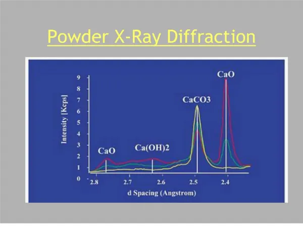
Scattered radiation 2q Sample Incident radiation Powder diffraction O X-ray powder diffraction pattern for cubic ZrW 2 8 6000 5000 4000 2q is the Bragg angle 3000 2dsinq=l or 2000 1000 0 1 1.5 2 2.5 3 3.5 4 4.5 5 Q
Common sample geometries • A slab of material in symmetrical reflection geometry • Most laboratory x-ray measurement • Absorption not usually a big problem because of the reflection geometry • A tube containing the sample • Most neutron experiments • Many synchrotron x-ray experiments and some laboratory experiments • Sample easily sealed and less susceptible to texture • Absorption can be a big problem with low energy x-rays as the beam has to pass through the sample q q 2q
X-ray tube • X-rays are usually produced in the lab using an x-ray tube. Electrons are accelerated onto a metal target
Tube emission spectra • Characteristic lines (atomic transitions) are superimposed on a continuous Bremsstrahlung background • Some lines are multiplets • This leads to a1/a2 splitting in powder diffraction patterns • Diffraction normally used the emission lines not the Bremsstrahlung • Intensity of K-line • IK = Bi(V-Vk)n • B proportionality constant, i current, V accelerating voltage, Vk threshold voltage, n ~ 1.5 Mo tube emission spectra taken from Cullity and Stock
Synchrotron radiation • High intensity • Plane polarized • Intrinsically collimated • Wide energy range • Has well defined time structure
Neutron Sources • Neutrons for diffraction are either produced using fission in a nuclear reactor or by spallation
Neutron sources 2 • Reactors produce neutrons continually (usually) • Spallation sources produce short pulses of neutrons • Neutrons are initially very energetic • They must be slowed down by moderation • Typically, exchange energy with a hydrogen containing material such as water, H2 or methane. Pulsed source peak flux Reactor flux Select narrow band for monochromatic diffraction Use wide band for time of flight diffraction
Powder diffraction at a reactor D2B Pictures courtesy of Alan Hewat
Sample L 2q L1 Source Detector Time-of-flight diffraction • Time from source to detector is determined by neutron wavelength • Can measure I(Q) without scanning detector • Use many separate detectors and sum the counts recorded in each to measure I(Q) with good counting statistics in less time and so
SEPD – Special Environment Powder Diffractometer • Only small fraction of total solid angle covered
X-rays with true 2D detectors: imaging plates, CCD cameras, multi-wires etc. • A true 2D detector can intercept complete cones of diffracted radiation and very efficiently record the diffraction pattern Fast data acquisition, but not very high resolution (Dd/d) Maximum 2q that is readily achievable is often quite limited
Integrating 2D data • Debye rings from the 2D detector are integrated and converted into a conventional powder pattern using FIT 2D or similar software X-ray beam size, detector pixel size and sample thickness combine to limit the effective resolution of the data
Why use 2D detectors? • Rapid acquisition of data from normal sized samples for time resolved or parametric studies • Seconds/minutes per pattern • Reasonable signal to noise and sampling statistics can be achieved even with very small samples such as those used in high pressure diamond anvil cell experiments Time resolution in this cement hydration experiment is ~5 minutes
Diamond anvil cell (DAC) • High pressures can be conveniently achieved by placing the sample between the faces of two diamonds and squeezing • Megabar pressures are attainable • Diamond does not absorb high energy x-rays strongly
1D detector: Debye-Scherrer camera • Can record sections on these cones on film or some other x-ray detector • Simplest way of doing this is to surround a capillary sample with a strip of film • Can covert line positions on film to angles and intensities by electronically scanning film or measuring positions using a ruler and guessing the relative intensities using a “by eye” comparison
Electronic 1D detectors • 1D position sensitive detectors based on many different types of technology are available. • Fast data collection, but not as efficient as a 2D detector • But access to high 2q by curving the detector INEL curved detector at Cal Tech Braun linear PSD at ORNL/HTML
X’celerator from Panalytical • Fast data collection using RTMS (Real Time Multiple Strip) detection technology Thanks to Panalytical
1 D detector in use for plate sample X’Celerator Scan direction Scan direction Divergence slit Line focus Polycrystalline sample Thanks to Panalytical
1 D detector with capillary sample Elliptical mirror Capillary sample or sample on/between foils Focus on (X’Celerator) detector Thanks to Panalytical
Capillary stage Thanks to Panalytical
Micro-diffraction 0.05 - 1 mm diameter X-ray tube X-ray tube Mono capillary (point focus) (point focus) X’Celerator Detector Small (part of) sample Microdiffraction Stage Thanks to Panalytical
Point detectors: Powder diffractometer • Alternatively, you can intercept sections of the cones using a point (0D) electronic detector Slit is moved to different 2qs. The x-rays passing through the slit are recorded electronically giving a powder pattern
Bragg Brentano diffractometer Detector Soller slits Curved crystal monochromator Receiving slit (Graphite) Anti scatter slit X-ray tube Soller slits (line focus) Polycrystalline sample Beam mask Divergence slit Thanks to Panalytical
X-ray optics • Conventional x-ray powder diffractometers use diverging x-ray beams, with the divergence limited by slits • If the effective sample surface is not on the 2q rotation axis, the peaks will be shifted from their correct positions by a “sample displacement” error • Many modern laboratory diffractometers use “parallel beam optics” that eliminate the problems of sample height displacement errors • Multilayer x-ray mirror on the incident beam side and Soller collimator on the diffracted beam side • Synchrotrons provide an inherently parallel beam on the incident side • Equipped with analyzer crystals on the diffracted beam side very high angular resolution can be achieved (see later). Insensitive to sample displacement. • Effective resolution of lab instruments can be improved by using Ka1 radiation only
Parallel beam geometry X-ray mirror Slit Parallel plate collimator + detector Polycrystalline sample
Parallel beam geometry X-ray mirror Slit Parallel plate collimator + detector Polycrystalline sample
Even a 1 mm displacement does not cause shifts! Data taken from T.R Watkins, Oak Ridge National Laboratory, USA
X’Celerator Soller slit Anti-scatter shield The 1-Reflection System Soller slits Irradiation slit Anti-scatter slit X-ray tube (line focus) Polycrystalline sample Incident beam Programmable monochromator divergence slit
Alpha-1 vs standard diffractometer Single peak No overlap Low background
Diffractometer Geometry • Crystal analyzer gives very good resolution, low count rate and is insensitive to sample displacement, useable with flat plate or capillary • Soller slits give modest resolution, good count rate and insensitivity to sample displacement • Simple receiving slits give good count rate, easily adjustable resolution, can be used with flat plate or capillary
Comparison of 2D and high res data 1BM/MAR345 – 1sec exposure 11BMB – 10min scan Thanks to R. Von Dreele
Energy discrimination • X-rays scattered from a sample can include unwanted wavelengths • Fluorescence, Kb, Bremmstrahlung….. • Can be eliminated using a diffracted beam monochromator • Typically graphite • Cheap, but you loose useful signal as well • Can be eliminated using an energy discriminating detector • Semiconductor “solid state detector” • Expensive, but can give good count rate
Collimator and EDX detector – at a fixed angle White X_ray Beam Diffraction patterns are Sample obtained only for the Environment volume subtended by the collimator with the incident X-ray beam Energy Dispersive Diffraction E(keV) = 6.199 / (d_space * sin(theta_angle of Energy Dispersive detector)) Courtesy of Lachlan
Energy Dispersive Diffraction : Advantages • Can see “inside” unconventional sample environments • Within limits: can have steel or other materials shielding the sample at pressure and/or temperature • thus samples can also be immersed in gas or liquid (hydrothermal synthesis) • in-situ studies - reactions / explosions / properties under stress. Particle flows within gases and fluids. Reactions in gas/fluid flow lines. • Only see diffraction in the volume (nick-named the “lozenge”) defined where the detector collimator subtends onto the incident white X-ray beam • Spatial Resolution inside the sample environment • Can narrow down the beam and collimator - and move the sample : thus obtaining diffraction patterns from different spatial volumes inside the sample environment • Fast data collection times • minutes to fractions of a second
Mapping phase distributions using EDXRD • Use EDXRD to record diffraction pattern from defined volumes inside specimens • map out the crystalline phases in the sample without damage
Summary • There are lots of experimental possibilities each one of which represents a trade off • Consider carefully which compromise works best for you