Download
1 / 37
370 likes | 498 Views
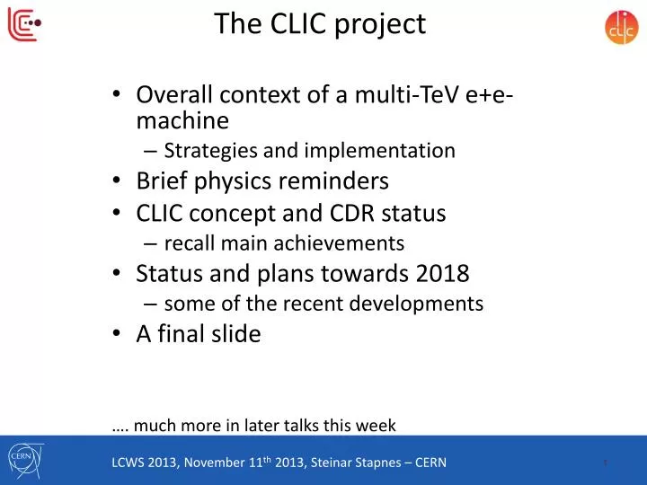
The CLIC project. Overall context of a multi- TeV e+e - machine Strategies and implementation Brief physics reminders CLIC c oncept and CDR status recall main achievements Status and plans towards 2018 s ome of the recent developments A final slide

E N D
The CLIC project • Overall context of a multi-TeVe+e- machine • Strategies and implementation • Brief physics reminders • CLIC concept and CDR status • recall main achievements • Status and plans towards 2018 • some of the recent developments • A final slide …. much more in later talks this week LCWS 2013, November 11th 2013, Steinar Stapnes – CERN
The context of the LC projects - strategies European Strategy priorities related to the Energy Frontier: • LHC and LHC luminosity upgrades (until ~2030) • Higgs and Beyond the Standard Model physics in long term programme • BSM – does it show up at LHC at 14 TeV, 2015 onwards ? • What are the best machines to access such physics directly post-LHC …. prepare main options the next years towards next strategy update (~2018) • Two main alternatives considered; higher energy hadrons (Future Circular Collider), or highest possible energy e+e- with CLIC • ILC in Japan, a possibility for exploring the Higgs in detail, starting at 250 GeV • If implemented a comprehensive programme that can in particular can map out the Higgs sector At CERN: In accordance with this, pursue three connected LC activities in the period towards 2017-18 (when LHC results at nominal energy are becoming mature): • CLIC as option for the energy frontier (accelerator, det&phys studies) – with links to FCC where appropriate • ILC project development - towards a construction project • Common activities wherever possible
CLIC for the energy frontier Goal for the next European Strategy update (2018):Present a CLIC project that is a “credible” option for CERN beyond 2030: • Physics studies updated taking into account LHC-14 TeV(assume the physics case will be there for an energy frontier machine – i.e. focus beyond the Higgs) • Physics after LHC programme completion (2030 +) • Initial costs and upgrade costs for 2nd and 3rd stage in reasonable agreement with one could hope based on CERN resources with additional international help – considering a 20-30 year perspective • Common/combined or coordinated studies with various of high energy hadron rings FCC, in particular related to CE, conv.system, costs, power, schedules, resources, some technical studies, physics studies (very little done in the last decade – see fig. right from 2001)
From Lucie Linssen CLIC reach for New Physics
Physics at Linear Colliders from 250 GeV to 3000 GeV • Physics case for the Linear Collider: • Higgs physics (SM and non-SM) • Top • SUSY • Higgs strong interactions • New Z’ sector • Contact interactions • Extra dimensions • …. AOP (any other physics) … • Specific challenges for CLIC studies therefore: • Need to address Higgs-studies, including gains for measurements at higher energies • Reach for various “new physics” (list above) options; comparative studies with HiLumi LHC, FCC … • See talk of Andre Sailer concerning (some of) these studies
CLIC Layout at 3 TeV Drive beam time structure - initial Drive beam time structure - final 240 ns 240 ns 5.8 ms 140 ms train length - 24 24 sub-pulses 4.2 A - 2.4 GeV – 60 cm between bunches 24 pulses – 101 A – 2.5 cm between bunches Drive Beam Generation Complex Main Beam Generation Complex
PossibleCLIC stages studied • Key features: • High gradient (energy/length) • Small beams (luminosity) • Repetition rates and bunch spacing (experimental conditions)
Conclusion of the accelerator CDR studies Main linac gradient • Ongoing test close to or on target • Uncertainty from beam loading being tested Drive beam scheme • Generation tested, used to accelerate test beam above specifications, deceleration as expected • Improvements on operation, reliability, losses, more deceleration studies underway TD24 baseline: Unloaded 106 MV/m Expected with beam loading 0-16% less CLIC Nominal, unloaded CLIC Nominal, loaded Luminosity • Damping ring like an ambitious light source, no show stopper • Alignment system principle demonstrated • Stabilisation system developed, benchmarked, better system in pipeline • Simulations on or close to the target • Start-up sequence and low energy operation defined • Most critical failure studied and first reliability studies Operation & Machine Protection Implementation • Consistent three stage implementation scenario defined • Schedules, cost and power developed and presented • Site and CE studies documented
The CLIC CDR documents In addition a shorter overview document was submitted as input to the European Strategy update, available at: http://arxiv.org/pdf/1208.1402v1 Input documents to Snowmass 2013 has also been submitted: http://arxiv.org/abs/1305.5766 and http://arxiv.org/abs/1307.5288
CLIC and ILC • Even though the basic acceleration technologies are different for CLIC and ILC, many areas have common challenges and potentially common solutions whenever the requirements are similar. • Among the most pronounced common activities:
Main activities and goals for 2018 Design and Implementation studies: • CDR status: not optimized except at 3 TeV and not adjusted for Higgs discovery, not optimized cost, first power/energy estimates without time for reductions, limited industrial costing, very limited reliability studies • Baseline design and staging strategy • Solid cost basis and more optimized power/energy (aim for 20% energy reduction) • Proof of industry basis for key components/units, in particular those specific for CLIC • Comprehensive reliability/robustness/uptime analysis • Pursue increased use of X-band for other machines/applications System-tests: • CDR status: CTF3 results initial phase (as of early 2012), ATF and FACET very little, no convincing strategy for further system verification • Complete system-tests foreseen for next phase, and comprehensive documentation of the results at CERN (CTF3) and elsewhere • Strategy for further system verification before construction (XFEL, connected to light-sources, further drive-beam verifications) or as part of initial machine strategy. • CDR status concerning drive-beam FE: Nothing done beyond CTF3 • Demonstrator of drive beam FE and RF power unit based on industrial capacity – will open for larger facilities beyond 2018 if necessary X-band developments: • CDR status: Single elements demonstrated – limited by test-capacity • Statistics for gradient and structure choice (energy reach) and other X-band elements Technology developments: • CDR status: alignment/stability partly covered, BBA assumed, wakefieldmon.perf. assumed, no complete module • Demonstration of critical elements and methods for the machine performance: • DR, main linac, BDS with associated instrumentation and correction methods (combination of design, simulation, system-tests and technologies) • Stability/alignment (locally and over distances) • Module including all parts
Will comment on all of these items briefly • Links strongly to many technical developments: design/modeling <-> technical developments <-> tests/verification
Possible luminosity examples – in CDR Based on 200 days/year at 50% efficiency (accelerator + data taking combined) Target figures: >600 fb-1 at first stage, 1.5 ab-1 at second stage, 2 ab-1 at third stage • Ongoing process: Iterate on energy choices • Stage optimised for ~350-375GeV for Higgs and top • 1-2 TeVdepending on physics findings, will still also do Higgs • 3 TeVas current ultimate energy, includes more Higgs • Consider in particular the initial stages: • Identify, review and implement cost and power/energy saving options • Identify and carry out required R&D • Re-optimise parameters (global design) • Develop an improved cost and power/energy consumption model • Iterations needed with saving options
Power/energy consumption • Considering 150 days per year of normal operation at nominal power and a luminosity ramp-up in the early years at each stage of collision energy, the development of yearly energy consumption can be sketched. • Re-optimize parts • Reduced current density in normal-conducting magnets • Reduction of heat loads to HVAC • Re-optimization of accelerating gradient with different objective function • Efficiency • Grid-to-RF power conversion • Permanent or super-ferric superconducting magnets • Energy management • Low-power configurations in case of beam interruption • Modulation of scheduled operation to match electricity demand: Seasonal and Daily • Power quality specifications • Waste heat recovery • Possibilities of heat rejection at higher temperature • Waste heat valorization by concomitant needs, e.g. residential heating, absorption cooling • Beyond: • Scale with inst. luminosity – i.e. running at the very end of the project lifetime might be power limited and require more time. CERN energy consumption 2012: 1.35 TWh
Cost/power reductions: some identified savings L-band klystron optimization studies • Use of permanent or hybrid magnets for the drive beam (order of 50’000 magnets) • Optimizedrive beam accelerator klystron system • Electron pre-damping ring can be removed with good electron injector • Dimension drive beam accelerator building and infrastructure are for 3TeV, dimension to 1.5TeV results in large saving • Systematic optimization of injector complex linacs in preparation • Power consumption: • Optimize and reduce overhead estimates
CLIC near CERN Tunnel implementations (laser straight) Central MDI & Interaction Region
Design -> Hardware -> Tests … Design/modeling -> Hardware -> Tests Emittance preservation feasibility for LC: mainly simulation studies Currently and next period: experimental studies of alignment methods • Test of prototype shows • vertical RMS error of 11μm • i.e. accuracy is approx. 13.5μm
Will comment mostly on CTF3 but note increased resources to development of full intensity drive-beam FE components such that we have prototypes/developments of all key part by 2018
CLIC Beam-Based Alignment tests at FACET Dispersion-free Steering (DFS) proof of principle – March 2013 • DFS correction applied to 500 meters of the SLC linac • SysID algorithms for model reconstruction • DFS correction with GUI • Emittance growth • is measured Orbit/Dispersion Graphic User Interface: Emittance SysID Beam profile measurement Incoming oscillation/dispersion is taken out and flattened; emittance in LI11 and emittance growth significantly reduced. Before correction After 1 iteration After 3 iterations
CLIC Test Facility / CTF3 Operation of isochronous lines and rings 4 A, 1.4us 120 MeV 30 A, 140 ns 120 MeV High current, full beam-loading operation Beam recombination and current multiplication by RF deflectors 12 GHz power generation by drive beam deceleration High-gradient two-beam acceleration 30 A, 140 ns 60 MeV Bunch phase coding
CTF3 programme 2013-2016 CLIC Diagnostics tests Phase feed-forward, DB stability studies Beam loading/BDR experiment Two-Beam Module, Wake-field monitors, Two-beam studies RF pulse shaping Power production, RF conditioning/testing with DB & further decelerator tests
Drive Beam phase feed-forward experiment CTF3 - Phase feed-forward Phase stability 0.2° @ 12GHz Fast kickers CLIC drive beam phase feed-forward concept Phase monitor Phase stability 2.5° @ 12GHz 0.2° @ 1GHz FONT5 board • Series of related studies: • Measure phase and energy jitter, identify sources, devise & implement cures, extrapolate to CLIC • Show principle of CLIC fast feed-forward Striplinekicker
Test Beam Line – Drivebeam deceleration 13 Power Extraction & Transfer Structures (PETS) installed and running in 2012 Full beam transport to end-of-line spectrometer, stable beam Power produced (70 MW/PETS) fully consistent with drive beam current (21 A) and measured deceleration. PETS tank during installation More than half a GW of 12 GHz power! TBL line in CLEX ~ 30 MeV 25% Beam deceleration, measured in spectrometer and compared with expectations
Two-Beam module into CTF3 Several mechanical complete modules are assembled, next: Installation and test of one full-fledged Two-Beam Module in CLEX CLEX module under fabrication/assembly, installation planned for mid 2014 • Completing the TBTS program: WF monitors, beam kicks, multi-poles… • Followed by module test program: • Basic RF behaviour (system conditioning, breakdown cross talks…). • Basic two-beam acceleration (energy gain, set-up with beam and phasing…). • Active alignment and stabilization, in presence of radiation and EM noise. • Alignment and fiducialization - WF monitors vsBPMs. • Phase drifts studies (thermal effects, losses…) Drive Beam line Main Beam line
NEXTEF at KEK ASTA at SLAC Previous: Scaled 11.4 GHz tests at SLAC and KEK. XBOX2 at CERN, industrial klystron ready next … then XBOX3 XBOX1 at CERN with SLAC klystron 100 MW can be provided in pulses of 250 ns, 50 Hz. Can power two CLIC accelerating structures. Planned capacity : power six CLIC accelerating structures Important goal: greatly increased X-band rf test capability, at 12 GHz, at CERN
CLIC main linac structure (12 GHz Cu TW) • 100 MV/m gradient (loaded) • BDR < 3 x 10⁻⁷/pulse/m • Rf pulse length: tp = 240 ns • Gradients depends on BDR and pulse-length, the lines represent the scaling to the correct BDR and pulse-length • TD24 structure (blue) at 106 MV/m unloaded (expect 0-16% less with loading) Still under conditioning
Experiment on the effect of Beam-Loading on BD rate • Beam loading reduces field locally in the structure ⇨ is it the break-down rate lower (or higher)? • Use CTF3 drive beam and klystron driven X-band structure • Measure BDR with/without beam to get a direct comparison Gradient along the structure DELAY LOOP Unloaded BL - BDR experiment COMBINER RING LINAC CLEX Average gradient 100 MV/m Increasing current Loaded (CLIC) RF 50 mm circular waveguide T24 structure installed in CTF3 Drive beam, 1-3A, 100-50 MeV
Several of these developments already mentioned in earlier slides; providing hardware for systemtestsand/or for assembled larger systems or specific studies • Will mentioned two: PACMAC Marie Curie Network with 10 Ph.D students, and the two beam module programme • Footnote: CLIC technology centreincluded costs for space preparation at CERN for CLIC activities in next period
Two beam module lab objectives • Build at least three mechanical modules for detailed tests in lab (plus one for CTF3 as mentioned) • Integration of all technical systems • Validation of different types of girders and movers • Pre-alignment of girders/quadrupoles in the module environment, • Full metrology of the module components • Validation of interconnections and vacuum systems under different thermal loads • Stabilization of main beam quad in the module environment • Vibration study of all systems and identification of vibration sources • Measurement of resonant frequencies • Simulation of several thermal cycles and alignment verification • Transport of the module and alignment verification CLIC Two-Beam Module Type 0 in B169
Fabricated RF mock-ups RF network PETS 8 Accelerating Structures
Test-area (simulating the tunnel) • Range for air temperature and speed: • Tair = 20 - 40 °C • vair = 0.2 - 0.8 m/s Heating coils • Air speed sensors installed in the middle of the room • The ceiling is movable for the transport test AIR FLOW AIR CIRCULATION transport test Air speed sensors Cooling coils
CLIC Collaboration 29 Countries – over 70 Institutes Acceleratorcollaboration Detectorcollaboration Accelerator + Detector collaboration
Link: http://indico.cern.ch/conferenceDisplay.py?confId=275412
Summary • CDR produced and feasibility demonstrated, providing input the strategy processes • The goals and plans for 2013-18 are well defined for CLIC, focusing on the energy frontier capabilities • Key challenges related to system specifications and performance, system tests to verify performances, technical developments of key elements, implementation studies including power and costs • A rebaselining of the machine stages with particular emphasis on optimising the staging of the machine, to be able react on LHC physics and possible guidance about the energy scales of new physics • The programme combines the resources of collaborators inside the current collaboration, plus several new ones now joining. Wherever possible common work with ILC is being implemented • Please see more in the talks given this week from many CLIC colleagues