Download
1 / 90
900 likes | 905 Views
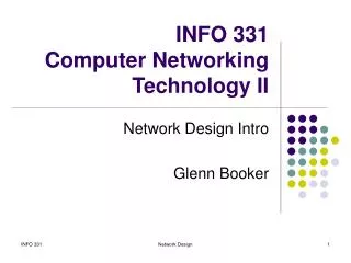
ECE 683 Computer Network Design & Analysis. Note 8: Packet Switching Networks (Network Layer Protocols). Outline. Network Services and Internal Network Operation Packet Network Topology Datagrams and Virtual Circuits Routing in Packet Networks Shortest Path Routing. Network Layer.

E N D
ECE 683Computer Network Design & Analysis Note 8: Packet Switching Networks (Network Layer Protocols)
Outline • Network Services and Internal Network Operation • Packet Network Topology • Datagrams and Virtual Circuits • Routing in Packet Networks • Shortest Path Routing
Network Layer • Network Layer: the most complex layer • Requires the coordinated actions of multiple, geographically distributed network elements (switches & routers) • Must be able to deal with very large scales • Billions of users (people & communicating devices) • Biggest Challenges • Addressing: where should information be directed to? • Routing: what path should be used to get information there?
t1 t0 Network Packet Switching • Transfer of information as payload in data packets • Packets undergo random delays & possible loss • Different applications impose differing requirements on the transfer of information
Messages Messages Segments Transport layer Transport layer Network service Network service Network layer Network layer Network layer Network layer Data link layer Data link layer Data link layer Data link layer End system β End system α Physical layer Physical layer Physical layer Physical layer Network Service • Network layer can offer a variety of services to transport layer • Connection-oriented service or connectionless service • Best-effort or delay/loss guarantees
Network Service Connectionless Datagram Transfer Connection-Oriented Reliable and possibly constant bit rate transfer Internal Network Operation Connectionless IP Connection-Oriented ATM Network Service vs. Operation Various combinations are possible • Connection-oriented service over Connectionless operation • Connectionless service over Connection-Oriented operation • Context & requirements determine what makes sense
C 3 2 1 2 1 2 2 1 1 End system α End system β 1 1 1 2 2 2 3 3 3 2 4 1 4 2 2 2 1 2 1 2 1 1 1 3 Medium 2 1 B A Network 3 1 Physical layer entity Network layer entity 3 Network layer entity Data link layer entity 2 4 Transport layer entity Complexity at the Edge or in the Core?
The End-to-End Argument for System Design • An end-to-end function is best implemented at a higher level than at a lower level • End-to-end service requires all intermediate components to work properly • Higher-level better positioned to ensure correct operation • Example: stream transfer service • Establishing an explicit connection for each stream across network requires all network elements (NEs) to be aware of connection; All NEs have to be involved in re-establishment of connections in case of network fault • In connectionless network operation, NEs do not deal with each explicit connection and hence are much simpler in design
Network Layer Functions Essential • Routing: mechanisms for determining the set of best paths for routing packets requires the collaboration of network elements • Forwarding: transfer of packets from NE inputs to outputs • Priority & Scheduling: determining order of packet transmission in each NE Optional: congestion control, segmentation & reassembly, security
Note 8: Packet Switching Networks Packet Network Topology
End-to-End Packet Network • Packet networks very different from telephone networks • Individual packet streams are highly bursty • Statistical multiplexing is used to concentrate streams • User demand can undergo dramatic change • Peer-to-peer applications stimulated huge growth in traffic volumes • Internet structure highly decentralized • Paths traversed by packets can go through many networks controlled by different organizations • No single entity responsible for end-to-end service
Access MUX To packet network Access Multiplexing • Packet traffic from users multiplexed at access to network into aggregated streams • DSL traffic multiplexed at DSL Access Mux • Cable modem traffic multiplexed at Cable Modem Termination System
r r • • • • • • nc r Nc Nr Oversubscription • Access Multiplexer • N subscribers connected @ c bps to mux • Each subscriber active r/c of time • Mux has C=nc bps to network • Oversubscription rate: N/n • Find n so that at most 1% overflow probability Feasible oversubscription rate increases with size
Home LANs • Home Router • LAN Access using Ethernet or WiFi (IEEE 802.11) • Private IP addresses in Home (192.168.0.x) using Network Address Translation (NAT) • Single global IP address from ISP issued using Dynamic Host Configuration Protocol (DHCP) WiFi Ethernet Home Router To packet network
LAN Concentration Switch / Router • LAN Hubs and switches in the access network also aggregate packet streams that flows into switches and routers
Campus Network Organization Servers Servers have redundant connectivity to backbone To Internet or wide area network s s Gateway Backbone R R R S S S R Departmental Server R R s s s High-speed campus backbone net connects dept routers Only outgoing packets leave LAN through router s s s s s s
Connecting to Internet Service Provider Internet service provider Border routers Campus Network Border routers Interdomain level Autonomous system or domain Intradomain level s LAN network administered by single organization s s
National Service Provider A National Service Provider B NAP NAP Private peering National Service Provider C Internet Backbone • Network Access Points: set up during original commercialization of Internet to facilitate exchange of traffic • Private Peering Points: two-party inter-ISP agreements to exchange traffic
National Service Provider A (a) National Service Provider B NAP NAP Private peering National Service Provider C (b) NAP RA RB Route Server LAN RC
Key Role of Routing How to get packet from here to there? • Decentralized nature of Internet makes routing a major challenge • Interior gateway protocols (IGPs) are used to determine routes within a domain • Exterior gateway protocols (EGPs) are used to determine routes across domains • Routes must be consistent & produce stable flows • Scalability required to accommodate growth • Hierarchical structure of IP addresses essential to keeping size of routing tables manageable
Note 8: Packet Switching Networks Datagrams and Virtual Circuits
Packet switching network Transfers packets between users Transmission lines + packet switches (routers) Origin in message switching Two modes of operation: Connectionless Virtual Circuit User Transmission line Network Packet switch Packet Switching Network
Message Message Message Source Message Switches Destination Message Switching • Message switching invented for telegraphy • Entire messages multiplexed onto shared lines, stored & forwarded • Headers for source & destination addresses • Routing at message switches • Connectionless
Source T t Switch 1 t Switch 2 t t Destination Delay Minimum delay = 3 + 3T over a path with two intermediate switches Message Switching Delay Additional queueing delays possible at each link
Approach 1: send 1 Mbit message Probability message arrives correctly On average it takes about 3 transmissions each hop Total # bits transmitted ≈ 6 Mbits (3 transmissions x 2 hops) source dest BER=p=10-6 BER=10-6 Long Messages vs. Packets 1 Mbit message How many bits need to be transmitted to deliver message? • Approach 2: send ten 100-kbit packets • Probability packet arrives correctly • On average it takes about 1/0.9=1.1 transmissions/hop • Total # bits transmitted ≈ 2.2 Mbits (1.1 x 2)
Packet 1 Packet 1 Packet 2 Packet 2 Packet 2 Packet Switching - Datagram • Messages broken into smaller units (packets) • Source & destination addresses in packet header • Connectionless, packets routed independently (datagram) • Packet may arrive out of order • Pipelining of packets across network can reduce delay, increase throughput • Lower delay than message switching, suitable for interactive traffic
t 1 3 2 t 3 1 2 t 1 2 3 t Delay Packet Switching Delay Assume three packets corresponding to one message traverse the same path with two switches Minimum Delay = 3τ + 5(T/3) (single path assumed) Additional queueing delays possible at each link Packet pipelining enables message to arrive sooner
Source t 1 3 2 Switch 1 t 3 1 2 Switch 2 t 1 2 3 t Destination L hops 3 hops L + (L-1)P first bit received 3 + 2(T/3) first bit received L + LP first bit released 3 + 3(T/3) first bit released 3 + 5 (T/3) last bit released L + LP + (k-1)P last bit released where T = k P Delay for k-Packet Message over L Hops
Route determined by table lookup Routing decision involves finding next hop in route to given destination Routing table has an entry for each destination specifying output port that leads to next hop Size of table becomes impractical for very large number of destinations Destination Output address port 0785 7 1345 12 1566 6 2458 12 Routing Tables in Datagram Networks
Example: Internet Routing • Internet protocol uses datagram packet switching across networks • Networks are treated as data links • Hosts have two-part IP address: • Network address + Host address • Routers do table lookup on network address • This reduces size of routing table • In addition, network addresses are assigned so that they can also be aggregated • Discussed as CIDR (classless interdomain routing) in Chapter 8
Packet Packet Packet Packet Virtual circuit Packet Switching – Virtual Circuit • Call set-up phase sets ups pointers in fixed path along network • All packets for a connection follow the same path • Abbreviated header identifies connection on each link • Packets queued for transmission • Variable bit rates possible, negotiated during call set-up • Delays variable, cannot be less than circuit switching
Connect request Connect request Connect request SW 1 SW n SW 2 … Connect confirm Connect confirm Connect confirm Connection Setup • Signaling messages propagate as a route is selected • Signaling messages identify connection and setup tables in switches • Typically a connection is identified by a local tag, Virtual Circuit Identifier (VCI) • Each switch only needs to know how to relate an incoming tag in one input to an outgoing tag in the corresponding output • Once tables are setup, packets can flow along path
t Connect request 1 3 2 CC t Release 3 CR 1 2 CC t Connect confirm 1 2 CR 3 t Connection Setup Delay • Connection setup delay is incurred before any packet can be transferred • Delay is acceptable for sustained transfer of large number of packets • This delay may be unacceptably high if only a few packets are being transferred
Each input port of packet switch has a forwarding table Lookup entry for VCI of incoming packet Determine output port (next hop) and insert VCI for next link Very high speeds are possible Table can also include priority or other information about how packet should be treated Input VCI Output port Output VCI 12 44 13 15 15 23 16 27 13 58 7 34 Virtual Circuit Forwarding Tables
Source t 2 1 3 Switch 1 t 2 3 1 Switch 2 t 2 1 3 t Destination Minimum delay = 3 + T Cut-Through switching • Some networks perform error checking on header only, so packet can be forwarded as soon as header is received & processed • Delays reduced further with cut-through switching
Message vs. Packet Minimum Delay • Message: L t + L T = L t + (L – 1) T + T • Packet L t + L P + (k – 1) P = L t + (L – 1) P + T • Cut-Through Packet (Immediate forwarding after header) = L t + T Above neglect header processing delays L-# of hops, t =Propagation time, T - a message’s transmission time, P=T/k, each packet’s transmission time
Note 8: Packet Switching Networks Routing in Packet Networks
1 3 6 4 2 Node (switch or router) 5 Routing in Packet Networks • Three possible (loopfree) routes from 1 to 6: • 1-3-6, 1-4-5-6, 1-2-5-6 • Which is “best”? • Min delay? Min hop? Max bandwidth? Min cost? Max reliability?
Creating the Routing Tables • Need information on state of links • Link up/down; congested; delay or other metrics • Need to distribute link state information using a routing protocol • What information is exchanged? How often? • Exchange with neighbors; Broadcast or flood • Need to compute routes based on information • Single metric; multiple metrics • Single route; alternate routes
Routing Algorithms • A routing algorithm: a decision algorithm of finding a path from a source to destination to efficiently deliver packets • Multiple paths: there may be many paths from a source to a destination, a routing algorithm is to find the BEST one! • Optimality: one’s meat is another’s poison! a criterion must be set before we talk about optimality
An example • An NJIT student • walk: does not cost anything but time (with additional benefit: exercise) • use a bike: you have to buy a bike • take a bus: cost a little (NJIT students get free ride?) but less convenient • drive: need to buy/rent a car, PARKING • take a taxi: cost a lot but less time • Which “path” is optimal? • Solution? Depends: need to consider money, time, convenience etc
Routing Algorithm Evaluation • Correctness: loop-free and deadlock-free • Simplicity: the simpler, the better • Robustness or Adaptability: cope with changes of topology and traffic and with failures • Stability: a stable path may be better • Fairness: fair to all packets/users/paths/routers • Optimality: in terms of indices according to network design objective • Efficiency: the less overhead, the better (information vs. overhead/control messages)
Algorithm vs Protocol • An algorithm is the method finding a path • An protocol is the implementation of a routing algorithm, may involve interface designs, information collection, route maintenance/route repair, reaction to various changes etc • Interchangeably used in some literature
Algorithm Classification • Depending on where and when an algorithm is executed, may have many types of algorithms • Static (fixed) vs. dynamic (adaptive) • Centralized vs. distributed
Static Routing • Static Routing • Routing paths are precomputed offline by a dedicated server based on network topology, link capacities and other information • Routing paths are loaded to nodes and remain fixed for a relatively long period • Works when traffic predictable & network is small and simple • React slowly to network failures, traffic load & network topology changes • Dynamic Routing • Each node calculates routes dynamically based on received updated network state information • Adapt quickly to changes in network conditions • Increased complexity in each node
Centralized vs Distributed Routing • Centralized Routing • All routes determined by a central node • All state information sent to central node • Problems adapting to frequent topology changes • Does not scale well • Distributed Routing • Routes determined by routers using distributed algorithm • State information exchanged by nodes • Adapts to topology and other changes • Better scalability • Inconsistent paths calculated by different nodes may lead to routing loops
2 7 1 8 B 1 3 3 A 6 5 1 5 4 2 VCI 4 Host Switch or router 3 5 2 5 C 6 D 2 Routing in Virtual-Circuit Packet Networks • Route determined during connection setup • Tables in switches implement forwarding that realizes selected route
Node 3 Incoming Outgoing Node 6 Node 1 Node VCI Node VCI 1 2 6 7 Incoming Outgoing Incoming Outgoing 1 3 4 4 Node VCI Node VCI Node VCI Node VCI 4 2 6 1 3 7 B 8 A 1 3 2 6 7 1 2 3 1 B 5 A 5 3 3 6 1 4 2 B 5 3 1 3 2 A 1 4 4 1 3 B 8 3 7 3 3 A 5 Node 4 Incoming Outgoing Node VCI Node VCI 2 3 3 2 Node 2 Node 5 3 4 5 5 Incoming Outgoing Incoming Outgoing 3 2 2 3 Node VCI Node VCI Node VCI Node VCI 5 5 3 4 C 6 4 3 4 5 D 2 4 3 C 6 D 2 4 5 Routing Tables in VC Packet Networks • Example: VCI from A to D • From A & VCI 5 → 3 & VCI 3 → 4 & VCI 4 • → 5 & VCI 5 → D & VCI 2
Node 3 Destination Next node Node 6 Node 1 1 1 Destination Next node Destination Next node 2 4 1 3 2 2 4 4 2 5 3 3 5 6 3 3 4 4 6 6 4 3 5 2 5 5 6 3 Node 4 Destination Next node 1 1 2 2 Node 2 Node 5 3 3 Destination Next node Destination Next node 5 5 1 1 1 4 6 3 3 1 2 2 4 4 3 4 5 5 4 4 6 5 6 6 Routing Tables in Datagram Packet Networks
Flat vs Hierarchical Routing • Flat Routing • All routers are peers • Does not scale • Hierarchical Routing • Partitioning: Domains, autonomous systems, areas... • Some routers are part of routing backbone • Some routers only communicate within an area • Efficient because it matches typical traffic flow patterns • Scales