Download
1 / 39
390 likes | 547 Views
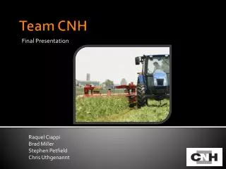
Team CNH. Mission Statement:. Design a less expensive propulsion control system with equivalent or better performance than existing hardware for Hydrostatic Windrower Machine. . Forward. Customer Wants. Low Cost Very Reliable Easy to Use Easy Maintenance High Level of Accuracy

E N D
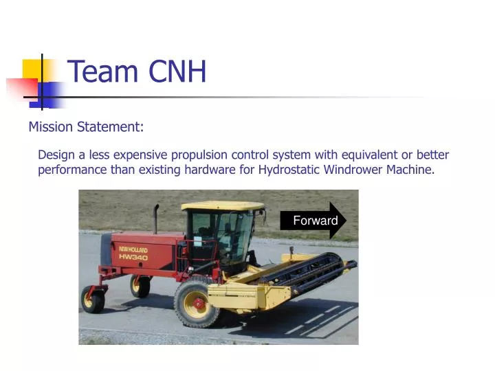
Team CNH Mission Statement: Design a less expensive propulsion control system with equivalent or better performance than existing hardware for Hydrostatic Windrower Machine. Forward
Customer Wants • Low Cost • Very Reliable • Easy to Use • Easy Maintenance • High Level of Accuracy • Comfortable to Use • Minimal Machine Redesign • Highly Repeatable • Continued Operation Ability • High Perception of Safety
Constraints • System Must Be Safe • System Must Meet all ASAE Codes • Total System < $300.00
Benchmarking Current CNH System
Benchmarking John Deere Hesston
Design Metrics • Time to Reach Neutral • Total Cost • Response Time • Serviceability Index • Component Effects • Energy Usage • Repeatability Rate • Number of Parts Changed
Design Target Values • Stopping Time < 10 Seconds • Total Cost < $250.00 • Response Time < ¼ Second • Serviceability Index < 237 • 12 Volt System, Draw < 30 Amps • Mean Time Between Failures > 3,240 Hours • Number of Parts Replaced <4
Motion Actuation Concept 1- Rotary Actuator
Motion Actuation Concept 2- Linear Actuator
Actuation Design Decision Chose to Use A Linear Actuator Because: • Least Expensive Solution • Smallest Amount of Machine Redesign • More Durability • Lowest Energy Requirements
Safety Return • Concept 1- Engine Shutoff Benefits: Least Expensive and Easiest to Implement Major Problems: Complete Loss of Operation After Failure Customer Perception of “Unsafe”
Safety Return Concept 2- Collapsible Linkage Normal Operating Conditions Failure Mode
Safety Return Concept 3-Hydrostatic Braking
Safety Return Concept 4- Hydro-Mechanical Failsafe
Safety Return Design Decision Chose the Hydro-Mechanical Failsafe Because: • Safe • Low Cost • Quick Time to Reach Neutral Position • Ability to Use Other Functions After Propulsion Shutoff
Reverse vs. Forward Engine Shutoff • Machine will not be cutting crop in reverse • Center of gravity is close to front of machine • Reverse speed much less than maximum forward speed • Machine will not be moving in reverse on roadways
Validation- Machine Tests How Will Machine React if Engine is Shutoff While Operating in Reverse?
Validation- Machine Tests Engine RPM Cylinder Position Ground Speed
Validation- FMEA • Failure Modes and Effects Analysis • Identifies Potential Failure Modes • Estimates Occurrence Rate • Assess Severity of Failure • Evaluates Potential To Detect Failure • Recommends a Design Action to Lower Risk if Needed
Path Forward • Finalize Actuator Supplier • Build Prototype • Write Controller Code • Test Mean Time Between Failure in Lab • Perform Field Tests
Spring Return Mechanism Existing CNH Return Spring
Hydraulic / Spring Connection To Pintel Arm To Spring Assembly Hydraulic Connection
Ci PWM Controller Diagram rd ed ri ei yi t yd Cd DC Motor Screw Linear actuator rd: Reference Displacement ed: Error Displacement Cd: Displacement Controller Ri: Reference Current Ei:Current Error Ci/PMW: Current Controller Yi: Output Current Yd:Output Displacement