Download
1 / 81
820 likes | 832 Views
An Introduction to Non-linear POD-based Reduced Order Models for Steady Aerodynamics Ralf Zimmermann Oberseminar Numerische Mathematik Kiel, February 11, 2010. DLR German Aerospace Center. Research Institution Space Agency Project Management Agency. Locations and employees.

E N D
An Introduction to Non-linear POD-based Reduced Order Models for Steady AerodynamicsRalf ZimmermannOberseminar Numerische MathematikKiel, February 11, 2010
DLR German Aerospace Center • Research Institution • Space Agency • Project Management Agency
Locations and employees 6000 employees across 29 research institutes and facilities at 13 sites. Offices in Brussels, Paris and Washington. nHamburg Bremen- n nNeustrelitz Trauen n Berlin- n Braunschweign nGoettingen nKoeln nBonn nLampoldshausen nStuttgart nOberpfaffenhofen Weilheimn
Guiding Principles – Vision DLR – one of Europe’s leading public research institutions, setting trends in its aeronautics, space, transport and energy business areas DLR – in its space agency function, a force that shapes European space activities DLR – the umbrella organisation for the most effective and efficient project management agencies and offices
National and International Networking World Europe Customers and partners: Governments and ministries, agencies and organisations, industry and commerce, science and research Germany
Research Areas Aeronautics Space Transport Energy Space Agency Project Management Agency
Aeronautics Slide 7
DLR Aeronautics Research Area Optimisation the performance and environmental compatibility of the entire aircraft system Expanding the range of helicopters to all weather conditions Efficient and environmentally-friendly aircraft engines Safe, environmentally-friendly and efficient air traffic (flight control, flight operations)
Space Slide 9
DLR Space Research Area Space exploration Zero gravity research Earth observation Communication and navigation Space transport Technology of space systems
Transport Slide 11
Challenges in the Transport Research Area Achieving sustainable mobility with balance between economy society ecology by ensuring the mobility of people and goods protecting the environment and resources improving safety
Energy Slide 13
DLR Energy Research Area DLR Energy Research concentrates on: CO2 avoidance through efficiency and renewable energies synergies within the DLR major research specific themes that are relevant to the energy economy
DLR Site Braunschweig Employees: 900 Size of site: 17 000 m² Research institutes and facilities: Institute of Aerodynamics and Flow Technology Institute of Composite Structures and Adaptive Systems Institute of Flight Guidance Institute of Flight Systems Institute of Transportation Systems DLR Design Office Flight operations Simulation and Software Technology (SISTEC) a section of the Koeln Institute of Air Transport and Airport Research Technology Marketing Training The Engineering Systems House (ESH) German-Dutch Wind Tunnels (DNW), Braunschweig low-speed wind tunnel << back
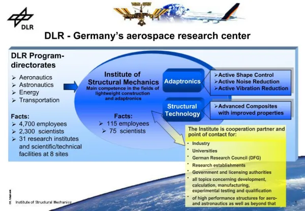
Institute of Aerodynamics and Flow TechnologyBraunschweig – Göttingen – KölnProf. C.-C. Rossow – Prof. A. Dillmann
Partners National International Airbus Germany ONERA, France EADS Military Aircraft, ST NLR, The Netherlands Eurocopter NASA, USA TU Braunschweig Centaur, USA / Greece RWTH Aachen AEDC, USA TU Berlin NAL, Japan University of Stuttgart ARA, UK TU MünchenTU Delft, The Netherlands JAXA, Japan
Customers National International Airbus Germany Airbus France EADS Military Aircraft, LFK, ST Airbus UK Eurocopter Germany European Commission Deutsche Lufthansa NLR, The Netherlands German Airports SNECMA, France German Government Authorities Dassault Aviation, France Rolls-Royce Germany ALCATEL, France IABG Alenia, Italy Rheinmetall ESA, Europe MAN CNES, France Bombardier GE Wind Energy BMW EADS-ST, France Volkswagen JAXA, Japan REPOWER Bayern Chemie Diehl BGT Defence OHB German Research Foundation (DFG)
Software Products CFD Methods • Structured RANS solver FLOWer • Hybrid RANS solver TAU • Higher-order DG solver PADGE • Structured grid generator MegaCads • Unstructured grid generator Centaur PIANO • CAA high resolution LEE/APE-solver • Stochastic source modeling RPM, … APSIM • FW-H/Kirchhoff-code UPM • Unsteady panel-method NOLOT/PSE • Flow stability code
Software ProductsIndustrial Applications EADS-MAS M = 0.75, Re = 3x10⁶ Eurocopter Germany EADS-MAS • DLR-Codes, FLOWer, TAU and PIANO used in German and European Aerospace industry Airbus
Institute Organization Institute of Aerodynamics and Flow Technology Management Prof. Rossow/Prof. Dillmann BS/GÖ Administration Dr. Weiland BS/ GÖ Configurative Design Dr. Heiko v. Geyr (komm.) BS C2A2S2E Prof. Kroll/Dr. Schwamborn BS/GÖ Exp. Methods Dr. Kompenhans GÖ Transport Aircraft Dr. Rudnik BS Spacecrafts Dr. Heinemann/Dr. Longo GÖ/BS High-Speed Config. Dr. Rosemann GÖ Technical Acoustics Prof. Delfs BS Technical Flows Prof. Raffel GÖ Wind Tunnels KP Dr. Gülhan KP Fluid Systems Prof. Wagner GÖ
Current Work of the Institute’s Departments C2A2S2E – Configurative Design – Transport Aircraft – Technical Acoustics Experimental Methods– High-Speed Configurations – Spacecrafts Technical Flows – Fluid Systems – Wind Tunnels KP
C²A²S²E – Center for Computer Applications in Aerospace Science and Engineering • Goal-oriented research environment • Integrated research, development and industrial application activities • Top-level research in the key areas of numerical simulation technology (physical modeling, numerical methods and information technology) • 3-pillars organization • Aerospace simulation center, development and application • Campus environment with leading experts and guest scientists • Professional hardware management and operation • Partnership for innovation • DLR • Airbus • Federal State of Niedersachsen
C²A²S²E (1)Simulation Center • Maneuver Simulation • Fully integrated interaction of major relevant disciplines • Aero-loads of the airplane in the whole flight envelope • Intelligent analysis of the flight envelope • Provision of all aerodynamic data for all components and total aircraft • Prediction of sensitivities – shaping the optimum • Digital prediction of “Flight Performance” and “Handling” prior to first flight • Investigation of flight scenarios and maneuvers • Full knowledge about aircraft behavior in flight • Virtual certification prior to production • Full knowledge of product characteristics • Fully guaranteed prediction accuracy
C²A²S²E (2-1)Objectives: Simulation of the Entire Flight Envelope • Real time flight maneuver simulation of complete aircraft • Aerodynamic: Unsteady Navier-Stokes-Simulations • Structure: Complete Finite-Element-Model of the aircraft • Flight Control: Complete flight maneuver simulation • Integration: Interaction of all disciplines • Estimated Aircraft Loads • Analyze of the complete flight envelope • Providing all aerodynamic data for the entire aircraft and components • Prediction of sensitivities – optimum
C²A²S²E (2-2)Objectives: Complete Simulation of the Aircraft • Flight performance prediction and flight characteristics prior to first flight • Analyze of flight-maneuver and –scenarios • Complete knowledge about flight characteristics of the aircraft • Certification of the virtual products prior to manufacturing • Complete knowledge about product characteristics and capabilities • Predictability guaranty
C²A²S²E (3) Cluster Hardware • 16 Compute Racks • 48 Blades • 2 x AMD Opteron Quad Core Processors 1,9 GHz (Barcelona) • 768 Knots • 758 Knots with 16 GB main memory • 10 Knots with 32 GB main memory • 6.144 cores = 46,6 Tflop/s (Peak Performance) • 12.288 GB main memory • Parallel File System
C²A²S²E (4)Virtual Reality • Visualization and analysis of complexflow fields • System • Powerwall 2.7m x 2.0m • 2 projectors • IR tracking system • Ensight Gold 8.2 visualization software
C²A²S²E (5)Expert Campus • Campus for excellent international scientists • 3-4 experts per year • Providing knowledge to find technical solutions • Intensive exchange with the team • Workshop and conferences • On major topics of the C2A2S2E center • For elaboration of innovative approaches and solutions • Training courses
Outline C2A2S2E Project: EnveLoad Surrogate modeling - the basic idea Proper Orthogonal Decomposition (POD) in a nutshell POD-based Reduced Order Modeling (ROM) Results Code validation Conclusions & Outlook
C2A2S2E – Center for Computer Application in AeroSpace Science and Engineering Digital Aircraft Vision DLR’s long-term objective • Time-accurate multi-disciplinary maneuvering aircraft simulations “Flying by the equations” • Generation of static & dynamic aerodynamic data-base, relying on high-fidelity tools “Flying through the data-base” [M.D. Salas, 2006], [M. Mavripilis, 2007]
Aero-LoadsPrediction Stefan Görtz Michael Mifsud Ralf Zimmermann Zhong-Hua Han Nicolas Gauger Britta Ernst Chunna Li C2A2S2E: Aero-Loads Prediction Group Long term objective • Development of a process chain for the efficient numerical prediction of all certification-relevant aerodynamic data for the aeroelastic aircraft over the entire flight envelope and beyond, incl. “fringes”, for all flight conditions and aircraft configurations, with guaranteed accuracy Main activities • Design of experiment (DoE) methods • Interpolation and Extrapolation methods • Variable-fidelity methods (VFM) • Reduced-Order Modeling • Surrogate-based optimization • Adjoint-based error estimation / uncertainties
Related Projects IMPULSE (2007-2010) ALEF(2009-2012) SimSac (2006-2009) FFAST (2009-2012) EnveLoad(2007-2012) ComFliTe(2009-2012) ARTEMIS (2008-20xx) AVT-161(2008-2010) IMPRADAL (2006-2008)
Outline Surrogate modeling - the basic idea Proper Orthogonal Decomposition (POD) in a nutshell POD-based Reduced Order Modeling (ROM) Results Code validation Conclusions & Outlook
Aerodynamic dataModeling Approach • Real world • I/O system • excitation / response • MISO / MIMO system • Simulation model (CFD) • approximation • discretization • Surrogate model • metamodel, RSM, emulator • scalable analytical model • “model of model” input output(s) output(s) input output(s) input
Simulation Model output • each new sample in input design space requires new computer simulation • accurate, high fidelity numerical model • However, simulation models... • ...complex • ...time consuming to run when used repetively • ...optimization is expensive • ...not always available • …highly specialized input output input2 input2 input1 input1
Scalable surrogate model, valid over design space output input output • continuous multi-dimensional model based on sampled data • one-time upfront investment • advantages • instant evaluation • compact formulation (few 100 parameters) • surrogate modeling challenges: • experimental design? • sample selection? • model type / model tuning? • surrogate models are still models • only as good as the available data / designer • model assessment & model selection are crucial input2 input2 out = f(in) input1 input1
What are we looking for? • Accuracy/speed trade-off • Best of both worlds • combining accuracy & generality of simulators, • with the speed & flexibility of models
Surrogate Model output • 4 key technologies • adaptive data sampling • adaptive model building • optimization • (distributed computing) input output input2 input2 out = f(in) input1 input1
MISO vs MIMO Surrogate Model scalar output input output input2 input2 out = f(in) input1 input1 • Problem: only suitable for scalar output Non-scalar output input output input2 out = f(in) input1 • Remedy: Proper Orthogonal Decomposition
design space DoE simulate sample distributedcomputing addextra samples build model adaptivesampling tunemodel adaptivemodeling assessmodel reflective exploration surrogatemodel Surrogate Modeling for Aero-data for Loads Generic Flow Chart
Outline Surrogate modeling - the basic idea Proper Orthogonal Decomposition (POD) in a nutshell POD-based Reduced Order Modeling (ROM) Results Code validation Conclusions & Outlook
Snapshots POD basis modes b POD a Proper Orthogonal Decomposition in a nutshell Reduced order POD basis Given: Design space spanned by set of snapshot vectors POD: Compute orthonormalbasis ordered by energy content spanning the same space => solution of eigenvalue problemrequired Restrict data representation and all computations of interest to the POD space. (e.g. flow reconstruction, interpolation, …)
Proper Orthogonal Decomposition in a nutshell Main Principle • Given a data set Y. - Interpret data as elements of a suitable vector space V of finite or infinite dimension - Choose a dimension k lower than or equal to the dimension of V - Find subspace S of V with the property that projection of the data on S is closest to the original data set, when compared to projection on all subspaces of the same dimension Tool for • data representation and analysis (original application) • interpolation • reduced order modeling (e.g. of dynamical systems via Galerkin Projection) Other names: Karhunen-Loève Decomposition, Principal Component Analysis
Proper Orthogonal Decomposition in a nutshell Representation of finite data sets Notation: • Input data: Each data vector is called a Snapshot. • Snapshot matrix:
Proper Orthogonal Decomposition in a nutshell Search optimal subspace to project data on. Mathematical formulation: Representation of finite data sets Lagrange approach leads to eigenvalue problem is called correlation matrix. It holds Ordered eigenvalues of Corresponding eigenvectors:
Proper Orthogonal Decomposition in a nutshell Optimal solution is given by ordered basis of eigenvectors now called POD basis; the eigenvectors are called POD modes. Representation of finite data sets For : -dimensional subspace “closest” to given data: Corresponding orthogonal projection: Reduced data representation:
Proper Orthogonal Decomposition in a nutshell Remark: Solving an eigenvalue problem of size “number of grid cells” is prohibitive! Representation of finite data sets Cure: Method of Snapshots (Sirovich, 1987) Observation: The non-zero eigenvalues of coincide. Let be the eigenvectors of resp. , corresponding to non-zero eigenvalues. Then Solution of the m m eigenvalue problem suffices to obtain the POD basis.
Proper Orthogonal Decomposition (POD) • Direct approach: Decompose • Singular value decomposition of • Method of snapshots (Sirovich 1987): Decompose Methods to obtain eigenvectors/ eigenvalues of the correlation matrix In all three cases the following two-step algorithm is applied • Transform input matrix to bidiagonal form • Compute EV-decomposition of quadratic non-zero block of bidiagonal form Hierarchy if (space dimension) #(snapshots): (A) (prohibitive) (B) (C) (LOT = lower order terms)
Proper Orthogonal Decomposition in a nutshell Choosing the ROM dimension : Relative Information Content: Choice depends on desired accuracy vs. computational costs. Rule of thumb: Choose such that (In many cases, the eigenvalues decrease exponentially, so that only a few of them contain the main information.)