Download
1 / 41
410 likes | 418 Views
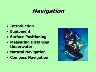
Navigation 404-03. Ground School. CI Pesto. Topics of discussion today. Map Construction Map Projections Aeronautical Charts Basic Chart Information Track The Canadian Flight Supplement. Maps and Charts.

E N D
Navigation404-03 • Ground School CI Pesto
Topics of discussion today • Map Construction • Map Projections • Aeronautical Charts • Basic Chart Information • Track • The Canadian Flight Supplement
Maps and Charts • A map is a small-scale flat-surface representation of some portion of the earth’s surface. • A representation that is designed for plotting navigational information is called a chart. • The earth is a sphere, so it must show the portion of earth with some distortion.
Four Basic Elements to Map Construction • There are four basic elements in map construction: • Areas, • Shapes, • Bearings, and • Distances.
Projections • The mathematical bases on which maps are constructed are termed projections. The three different types of Projections are; - Lambert Conformal Conic Projection - Mercator Projection - Transverse Mercator Projection
Lambert Conformal Conic Projection Concept supposes a cone superimposed over the surface of a sphere.
Lambert Cont. • PROPERTIES • Meridians of longitude converge toward the nearer pole. • Parallels of latitude are curves which are concave toward the nearer pole. • The scale is almost perfectly uniform. • A straight line drawn on this map is a GREAT CIRCLE.
Mercator Projection • Based on the fact that a cylinder has its tangency at the Equator. • Can be visualized as a light radiating out from the centre of the earth projecting image outwards onto a cylinder.
Mercator Cont. • Meridians of longitude are straight and parallel. • Parallels of latitude are straight and parallel. • There is no constant scale. • A straight line drawn on this map is a RHUMB LINE. • There is extreme exaggeration of longitude in northerly areas. • Distances shown near the equator are fairly precise.
Transverse Mercator Projection • Same technique as Mercator Projection except the cylinder is rotated 90 degrees so that point of tangency is a meridian of longitude rather than the Equator. • Chart is accurate along the selected meridian.
Transverse Mercator Projection Cont. • Quite accurate at depicting scale. • Distance is accurate along the meridian • Distortion occurs at the edges of the map. Similar to Mercator Projection except:
Aeronautical Charts • VFR Navigation Chart • World Aeronautical Chart (WAC) • VFR Terminal Area Chart (VTA) • Enroute Charts
VFR Navigational Chart • Depict more extensive geographical areas, • Chart printed on both sides, • Chart is identified by the name of principle landmark,
VFR Cont. • Based on Lambert Conformal Conic Projection, • Useful during flights at lower altitudes and slower speeds, • Scale is 1:500,000.
World Aeronautical Chart (WAC) • Designed for visual navigation at higher altitudes and greater speeds, • Each chart depicts a sizeable portion of a geographical area, • Each chart is identified by a letter and a number, • Printed on both sides, • Scales is 1:1,000,000.
VFR Terminal Area Charts (VTA) • Large-scale charts (1:250,000) published for those airports in Canada which have been designated as classified airspace for control purposes, • Based on Transverse Mercator Projection.
Enroute Charts • Low altitude charts are for altitudes less than 18,000 feet and high altitude charts are for altitudes equal to or greater than 18,000 feet. • Provide information for radio navigation over designated airways system …. very little visual information. • Its scale is not consistent.
Basic Chart Information Maps have a number of properties including • Represents a portion of the earth • Has meridians of longitude and parallels of latitude • Scale* • Relief* • Isogonic Lines
Chart Info Cont. • Communities, roads and railways • Aerodromes • Restricted areas • Compass Rose • Aeronautical Information
*Scale • Scale is a relationship between a unit of distance on the map to the distance on the earth that the unit represents. Two methods include:
-Representative Fraction Scale • Most common method of expressing map scale. • Expresses the ratio of a unit of length of the map to a corresponding number of similar units on the earth.
-Graduated Scale • A line drawn on some convenient part of the map and graduated to show the length of one mile on the map.
*Relief • A representation of ground elevation above sea level on aeronautical maps. There are three ways to show relief on a map: • Layer Tinting • Contour Lines • Spot Heights
-Layer Tinting • When the map is coloured to represent different levels of elevation. • An elevation legend is printed on the white border of every map to show what colours are used for different elevations.
-Contour Lines • Lines drawn on a chart joining points of equal elevation above mean sea level. • The gradient of a slope is indicated by the horizontal distance between the contour lines.
-Spot Heights • When high elevations are marked by a dot with the spot height written beside the dot. • The highest spot height in a quadrant is usually printed in larger numbers than the other spot heights.
The Canadian Flight Supplement • Lists all aerodromes shown on VNC's and WAC's. • It also contains all kinds of valuable information related to aviation and is absolutely invaluable to a pilot.
Track • The direction the aircraft intended to take over the ground. • May be represented by a straight line drawn on a map. Also known as intended track or required track. • Direction is the angle between this line and a meridian measured clockwise through 360 degrees. Can be true magnetic or compass.
Track Made Good • Actual path traveled by the aircraft over the ground. • Line track it may be represented by a line drawn on a map and its direction measured (if it is reasonably straight line).
Drift • Drift or drift angle, is the angle between the heading being flown and the track made good over the ground. It can be expressed in degrees either left or right.
Make sure to go over todays information because there’s a lot of it!! • FTGU Chart Section- pages 184 to 195 • Ask Questions! • Quiz Next Class