Download
1 / 12
120 likes | 123 Views
Learn how to analyze circuits using resistors in series and parallel and apply Kirchhoff's Rules for more complex circuits. Solve example problems step-by-step.

E N D
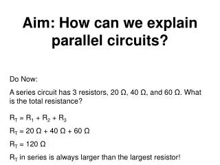
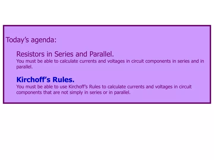
Today’s agenda: Resistors in Series and Parallel. You must be able to calculate currents and voltages in circuit components in series and in parallel. Kirchoff’s Rules. You must be able to use Kirchoff’s Rules to calculate currents and voltages in circuit components that are not simply in series or in parallel.
h 30 I1 I3 40 1 2 = 45 V a d c b 20 I2 1 = 85 V 1 g e f Kirchhoff’s Rules No, it is pronounced “KEERKOFF’s” rules. The ch sounds like “k,” not like “ch.” (depending on regional accents) Analyze this circuit for me, please. Find the currents I1, I2, and I3.
h 30 I1 I3 40 1 2 = 45 V a d c b 20 I2 1 = 85 V 1 g e f I see two sets of resistors in series. This. And this. You know how to analyze those. Further analysis is difficult. For example, series1 seems to be in parallel with the 30 resistor, but what about 2? We haven’t discussed how to analyze that combination. series1 series2
A new technique is needed to analyze this, and far more complex circuits. Kirchhoff’s Rules Kirchhoff’s Junction Rule: at any junction point, the sum of all currents entering the junction must equal the sum of all currents leaving the junction. Also called Kirchhoff’s First Rule.* Kirchhoff’s Loop Rule: the sum of the changes of potential around any closed path of a circuit must be zero. Also called Kirchhoff’s Second Rule.** *This is just conservation of charge: charge in = charge out. **This is just conservation of energy: a charge ending up where it started out neither gains nor loses energy (Ei = Ef ).
Kirchhoff’s Rules Starting Equations You already used this in your homework! simple… but there are details to worry about…
If this were Physics 1135, you would have a Kirchhoff’s Rules litany. You have my permission to print this page and use it for tomorrow’s boardwork. Brief litany for Kirchhoff’s Rules Problems 1. Draw the circuit. 2. Label + and – for each battery. 3. Label the current in each branch of the circuit with a symbol and an arrow (OK to guess direction). 4. Apply Kirchhoff’s Junction Rule at each junction. Current in is +. 5. Apply Kirchhoff’s Loop Rule for as many loops as necessary. Follow each loop in one direction only. + 5a. Resistor: I 5b. Battery: V is + - V is - loop loop 6. Solve.
h 30 I1 I3 40 1 2 = 45 V a a d d c b 20 I2 1 = 85 V 1 g e f Back to our circuit: we have 3 unknowns (I1, I2, and I3), so we will need 3 equations. We begin with the junctions. Junction a: I3 – I1 – I2 = 0 --eq. 1 Junction d: -I3 + I1 + I2 = 0 Junction d gave no new information, so we still need two more equations.
h 30 I1 I3 40 1 2 = 45 V a d c b 20 I2 1 = 85 V 1 g e f Loop 1. Loop 2. Loop 3. There are three loops. Any two loops will produce independent equations. Using the third loop will provide no new information.
h 30 I1 I3 40 1 2 = 45 V a d c b 20 I2 1 = 85 V 1 g e f The “green” loop (a-h-d-c-b-a): (- 30 I1)+ (+45) + (-1 I3) + (- 40 I3) = 0 (- 30 I1) + (+45)+ (-1 I3) + (- 40 I3) = 0 (- 30 I1) + (+45) + (-1 I3)+ (- 40 I3) = 0 (- 30 I1) + (+45) + (-1 I3) + (- 40 I3)= 0 (- 30 I1) + (+45) + (-1 I3) + (- 40 I3) = 0 I + - V is - V is + loop loop
h 30 I1 I3 40 1 2 = 45 V a d c b 20 I2 1 = 85 V 1 g e f The “blue” loop (a-b-c-d-e-f-g): (+ 40 I3) + ( +1 I3) + (-45) + (+20 I2) + (+1 I2) + (-85) = 0 (+ 40 I3) + ( +1 I3) + (-45) + (+20 I2) + (+1 I2) + (-85)= 0 (+ 40 I3) + ( +1 I3) + (-45) + (+20 I2) + (+1 I2) + (-85) = 0 (+ 40 I3) + ( +1 I3) + (-45) + (+20 I2) + (+1 I2) + (-85) = 0 (+ 40 I3) + ( +1 I3)+ (-45) + (+20 I2) + (+1 I2) + (-85) = 0 (+ 40 I3) + ( +1 I3) + (-45) + (+20 I2) + (+1 I2) + (-85) = 0 (+ 40 I3) + ( +1 I3) + (-45)+ (+20 I2) + (+1 I2) + (-85) = 0 I + - V is - V is + loop loop
After combining terms and simplifying, we now have three equations, three unknowns; the rest is “just algebra.” Junction a: I3 – I1 – I2 = 0 --eq. 1 The “green” loop - 30 I1 + 45 - 41 I3 = 0 --eq. 2 The “blue” loop 41 I3 -130 + 21 I2 = 0 --eq. 3 skip the algebra! Make sure to use voltages in V and resistances in . Then currents will be in A. You can see the solution in part 7 of today’s lecture notes (which will not be presented in class). It’s a pain. Generally, with the homework problems, you can easily solve directly for one variable, leaving you with two equations and two unknowns.
Don’t forget… eat your oreos!